Home>Garden Essentials>How To Use AutoCAD For Landscape Design
Garden Essentials
How To Use AutoCAD For Landscape Design
Modified: October 20, 2024
Learn how to use AutoCAD for landscape design and create stunning garden layouts. Discover step-by-step tutorials, tips, and techniques to bring your garden designs to life.
(Many of the links in this article redirect to a specific reviewed product. Your purchase of these products through affiliate links helps to generate commission for Storables.com, at no extra cost. Learn more)
Introduction
Welcome to the world of landscape design! If you have a passion for gardening and a creative eye, learning how to use AutoCAD for landscape design can take your skills to the next level. AutoCAD, a popular computer-aided design (CAD) software, offers powerful tools and features that enable you to create detailed and professional landscape designs.
AutoCAD is widely used in various industries, including architecture, engineering, and construction. However, its capabilities extend beyond just creating buildings and structures. With the right knowledge and techniques, you can harness the power of AutoCAD to bring your gardening ideas to life and transform outdoor spaces into stunning landscapes.
By utilizing AutoCAD’s precision and efficiency, you can design intricate garden layouts, plan the placement of plants, create irrigation systems, and visualize your designs in 3D. Whether you’re a professional landscape designer or an enthusiastic gardener looking to improve your skills, this guide will walk you through the essentials of using AutoCAD for landscape design.
In this article, we’ll cover everything you need to know to get started with AutoCAD for landscape design. We’ll explore the key features and tools that will help you create accurate and visually appealing designs. From drawing basic shapes to adding text and dimensions, customizing the workspace to utilizing libraries and templates, we’ll guide you through the process step by step.
Throughout the article, we’ll also provide valuable tips and insights to help you optimize your designs and make the most of AutoCAD’s capabilities. So, whether you’re designing a small backyard garden or a large-scale landscape project, this guide will equip you with the knowledge and skills to turn your vision into a reality.
Now, let’s dive into the world of AutoCAD for landscape design and unleash your creativity!
Key Takeaways:
- AutoCAD offers powerful tools for creating detailed and professional landscape designs. It provides flexibility, precision, and efficiency to bring gardening ideas to life, making it a valuable tool for landscape designers and gardening enthusiasts alike.
- Leveraging AutoCAD libraries and predefined templates streamlines the design process, saving time and effort. Exporting and sharing CAD drawings ensures seamless collaboration and communication with clients and stakeholders, enhancing the accessibility and compatibility of designs.
Read more: How To Design A House Plan Using AutoCAD
Understanding AutoCAD for Landscape Design
Before diving into the practical aspects of using AutoCAD for landscape design, it’s essential to understand the fundamentals of this powerful software. AutoCAD is a CAD program developed by Autodesk that allows users to create precise, detailed, and scalable drawings. It provides a wide range of tools and features specifically tailored for design and drafting purposes.
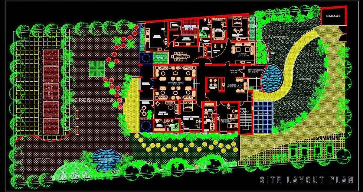
In the context of landscape design, AutoCAD provides the means to create accurate drawings of outdoor spaces, including gardens, parks, and recreational areas. It enables you to visualize and plan the layout of elements such as plants, trees, pathways, water features, and structures.
One of the key advantages of using AutoCAD for landscape design is the ability to create drawings with precision. You can specify exact dimensions, angles, and distances, ensuring that your designs are accurate and to scale. This level of precision is crucial when planning and implementing your landscape designs.
AutoCAD also offers a wide range of design tools that can streamline your workflow and enhance your creativity. From drawing basic shapes and lines to adding advanced elements like hatches, gradients, and annotations, AutoCAD provides the flexibility to create intricate and visually appealing landscape designs.
Another crucial feature of AutoCAD is its ability to generate 3D representations of your landscape designs. This allows you to visualize your ideas in a three-dimensional space, giving you a realistic perspective of how the final project will look. With 3D modeling, you can accurately evaluate the spatial relationships between different elements and make informed design decisions.
Furthermore, AutoCAD allows you to generate accurate measurements, quantities, and material lists. This can be beneficial when estimating costs, planning material requirements, and collaborating with contractors or suppliers.
Overall, AutoCAD is a versatile and powerful tool for landscape design. It combines precision, creativity, and efficiency to help you bring your outdoor spaces to life. By understanding the capabilities and features of AutoCAD, you can leverage its potential to create stunning and functional landscape designs.
In the next sections of this guide, we will delve into the practical aspects of using AutoCAD for landscape design. We will explore the essential tools and techniques that will empower you to design and visualize your dream landscapes. So, let’s get started with creating a new drawing in AutoCAD!
Getting Started with AutoCAD
Now that you have a basic understanding of AutoCAD for landscape design, it’s time to get started with the software. In this section, we will walk you through the initial steps of setting up AutoCAD and creating a new drawing.
After launching AutoCAD, you will be greeted with the application’s interface. The interface consists of various elements such as the toolbar, ribbon, command line, and drawing area. Familiarizing yourself with these elements will help you navigate and utilize AutoCAD effectively.
To create a new drawing, you can either click on the “New” button in the toolbar or use the “New” command in the command line. This will open a new drawing template where you can begin your landscape design.
AutoCAD offers a variety of drawing templates, including general-purpose templates and specialized templates for specific industries. For landscape design, it is recommended to choose a template that is suitable for architectural or landscape design purposes.
Once you have selected a template, you will be presented with a blank canvas to start drawing. By default, AutoCAD uses a grid system to help you maintain accuracy in your designs. You can adjust the grid settings based on your preference or project requirements.
Before diving into the drawing process, it’s essential to familiarize yourself with the navigation tools in AutoCAD. These tools allow you to zoom in and out, pan across the drawing area, and rotate the view. You can access these tools through the toolbar or by using keyboard shortcuts.
Now that you’re equipped with the basic setup and navigation knowledge, it’s time to start creating your landscape design. AutoCAD provides a wide range of drawing tools that allow you to create shapes, lines, curves, and polygons.
For landscape design, you will often use tools like the line, polyline, rectangle, circle, and arc. These tools enable you to create the basic structure and layout of your design. By combining and modifying these shapes, you can define the features and elements of your landscape.
As you start drawing, make sure to pay attention to scale and dimensions. AutoCAD allows you to input precise measurements for each element, ensuring accuracy and consistency in your design. You can use the “Command Line” or “Properties” panel to input specific dimensions.
Additionally, AutoCAD provides tools for mirroring, copying, and offsetting objects, which can help you create symmetrical designs and replicate elements with ease. Understanding these tools and their functionalities will save you time and effort during the design process.
Remember to save your progress regularly to avoid losing your work. AutoCAD allows you to save your drawings in various formats, including DWG and DXF, which are widely supported in the industry.
In the next sections, we will delve deeper into customizing the workspace, using layers and lineweights, and adding text and annotations to enhance your landscape design. So, let’s continue our AutoCAD journey and bring your designs to life!
Creating a New Drawing
Creating a new drawing is the first step in using AutoCAD for landscape design. A new drawing serves as a blank canvas where you can bring your design ideas to life. In this section, we’ll guide you through the process of creating a new drawing in AutoCAD.
When you launch AutoCAD, you’ll be presented with the application’s interface. To create a new drawing, you have several options. One way is to click on the “New” button located in the toolbar. Alternatively, you can use the “New” command by typing it in the command line.
Upon selecting the “New” option, a dialog box will appear, prompting you to choose a template for your new drawing. AutoCAD provides a variety of templates to cater to different design disciplines, including architecture and landscape design. You can browse through the available templates or search for a specific one using keywords.
For landscape design, it’s recommended to select a template that aligns with your project requirements. Look for templates labeled “Architectural” or “Landscaping” to ensure that the drawing units and scale are suitable for your designs.
Once you’ve chosen a template, click on the “Open” button to create a new drawing based on that template. AutoCAD will then load the template with a preset layout and settings, ready for you to start your design.
The new drawing will open in the drawing area, which is the main workspace where you’ll be creating your landscape design. AutoCAD provides a grid system that helps you maintain accuracy and alignment in your drawings. You can customize the grid spacing and visibility based on your preferences and project requirements.
Now that you have a blank canvas, you can begin adding elements to your drawing. AutoCAD offers various drawing tools that allow you to create lines, shapes, and curves. These tools can be accessed from the toolbar, ribbon, or by typing specific commands in the command line.
As you start drawing, it’s important to pay attention to scale and dimensions. AutoCAD allows you to input precise measurements for each element, ensuring accuracy in your design. You can specify the dimensions of lines, shapes, and angles using the “Command Line” or the “Properties” panel.
In addition to the drawing tools, AutoCAD provides additional features such as layers, lineweights, and colors that enable you to organize and distinguish different elements in your design. By utilizing layers, you can group related objects together and control their visibility and properties.
Remember to save your drawing periodically to avoid losing your progress. AutoCAD allows you to save your drawings in various file formats, including DWG and DXF. These formats are widely compatible and can be easily shared with others.
Now that you have created a new drawing, it’s time to dive deeper into the exciting features and tools of AutoCAD for landscape design. In the next sections, we’ll explore customizing the workspace, adding text and annotations, and utilizing hatch patterns and gradients to enhance your landscape designs.
Customizing the Workspace
Customizing the workspace in AutoCAD allows you to tailor the interface and tools to your preferences, making your workflow more efficient and productive. In this section, we’ll explore the different ways you can customize the AutoCAD workspace for landscape design.
AutoCAD provides multiple interface elements that can be customized, including the ribbon, toolbars, menus, and palettes. These elements contain various commands and tools that you can access to perform different tasks in your landscape design.
To begin customizing the workspace, click on the “Workspace” menu in the upper-right corner of the AutoCAD window. Here, you can choose from a list of predefined workspaces, such as “Drafting & Annotation,” “3D Modeling,” or “Customize.” Selecting a workspace will modify the arrangement of the interface elements based on the intended workflows.
If none of the predefined workspaces suit your needs, you can create a custom workspace by selecting the “Customize Workspace” option. This allows you to modify the layout and content of the interface elements according to your preferences.
Customizing the ribbon is another way to personalize your AutoCAD workspace. The ribbon contains various tabs, panels, and tools categorized based on their functions. To customize the ribbon, right-click on it and select the “Customize the Ribbon” option.
In the customization window, you can add or remove tabs, panels, and commands to create a customized ribbon that fits your workflow. This enables you to have quick access to the tools and commands that are most frequently used in your landscape design process.
AutoCAD also allows you to create and customize toolbars, which can provide quick access to specific commands and tools. To customize the toolbars, right-click on an empty area in the toolbar section and select “Customize.” Here, you can add or remove buttons, rearrange their order, and create your own custom toolbars.
In addition to the ribbon and toolbars, AutoCAD offers palettes that provide a way to access specific tools and features. Palettes can be docked to different areas of the user interface or floated as separate windows. You can customize and arrange palettes based on your preference and frequently used features.
Another aspect of customizing AutoCAD’s workspace is configuring the display and visual settings. AutoCAD allows you to change the color scheme, background, and visual styles of the interface. Personalizing these settings can enhance your visual experience and reduce eye strain during long design sessions.
Once you have customized the workspace to your liking, you can save your changes as a new workspace configuration. This allows you to switch between different workspace setups based on the specific tasks or projects you are working on.
By customizing the AutoCAD workspace, you can create an environment that is tailored to your needs and preferences. This enhances your productivity and efficiency when designing landscapes, as you can focus on the tools and commands that are most important to your workflow.
Now that you have personalized your AutoCAD workspace, it’s time to dive into the specifics of landscape design. In the next sections, we’ll explore drawing basic shapes, using layers and lineweights, and adding text and annotations to your landscape designs.
Read more: What Is AutoCAD
Setting up Drawing Units
Setting up the drawing units in AutoCAD is essential for ensuring accuracy and consistency in your landscape designs. Drawing units determine the scale and measurement system used in your drawings. In this section, we’ll guide you through the process of setting up the drawing units in AutoCAD.
To access the drawing units settings, click on the “Unit” button located in the bottom-right corner of the AutoCAD window. Alternatively, you can type the “UNITS” command in the command line.
When the drawing units dialog box appears, you’ll see several options to configure the units for length, angle, area, and other measurements. In the “Length” section, you can choose the desired unit format, such as inches, feet, meters, or millimeters.
Selecting the appropriate unit format depends on the scale of your landscape design and the standard measurement system used in your region. For example, if you’re working on a large landscape project, using meters or feet may be more suitable. On the other hand, if you’re designing a small garden, inches or millimeters may provide more precision.
It’s important to note that once you set the drawing units, all the measurements you input in AutoCAD will be based on that unit format. Therefore, it’s crucial to choose the correct unit format and be consistent throughout your drawings.
AutoCAD also allows you to specify the precision of measurements by adjusting the number of decimal places. This can be useful when working with intricate designs that require high levels of accuracy. However, keep in mind that using too many decimal places can result in larger file sizes and potentially cause compatibility issues.
In addition to length units, you can also configure the units for angles, area, volume, and other measurements. The angle units can be set in degrees, radians, or grads. You can choose the desired unit format that aligns with your project requirements.
Once you have configured the drawing units to your liking, click on the “OK” button to apply the changes. AutoCAD will now use the specified units for all your measurements and calculations.
Using the correct drawing units ensures that your design is accurately scaled and can be easily understood by others who may be working on the project or reviewing your drawings. It also simplifies the process of generating accurate measurements and quantities for estimating costs and planning material requirements.
Remember to consider the standard practices and measurement systems used in your region or industry when setting up the drawing units. By aligning your drawings with the accepted standards, you ensure consistency and improve communication with other professionals involved in the landscape design process.
Now that you’ve set up the drawing units in AutoCAD, it’s time to start drawing basic shapes and creating the groundwork for your landscape design. In the next section, we’ll explore the tools and techniques for drawing basic shapes in AutoCAD.
Drawing Basic Shapes
One of the fundamental aspects of using AutoCAD for landscape design is the ability to create and manipulate basic shapes. These shapes serve as the building blocks for your landscape design, allowing you to define the layout and structure of different elements. In this section, we’ll explore the tools and techniques for drawing basic shapes in AutoCAD.
AutoCAD provides several tools that enable you to create various basic shapes, such as lines, circles, rectangles, polygons, and arcs.
To draw a line, simply select the “Line” tool from the toolbar or type the “LINE” command in the command line. Click on the starting point of the line, then click on the end point to define its length and direction.
The circle tool allows you to draw perfect circles. You can access the circle tool from the toolbar or by typing the “CIRCLE” command. Specify the center point of the circle and its radius, diameter, or circumference.
Similarly, the rectangle tool enables you to draw precise rectangular shapes. Use the toolbar or type the “RECTANG” command to access the rectangle tool. Specify opposite corners or use length and width values to define the dimensions of the rectangle.
To create polygons, AutoCAD offers the “POLYGON” tool. Select the tool from the toolbar or type the “POLYGON” command. Specify the center point, number of sides, and radius or diameter to draw a regular polygon.
The arc tool in AutoCAD allows you to draw arcs of different sizes and angles. You can access the arc tool from the toolbar or by typing the “ARC” command. Specify the arc’s start point, the center, and the end point or use other parameters such as radius or angle to define the arc.
Combining these basic shapes, you can create complex layouts and structures for your landscape designs. For example, you can use lines to define walkways or borders, circles to represent trees or flower beds, rectangles to indicate structures like buildings or gazebos, and polygons to outline irregular areas or ponds.
AutoCAD provides additional tools and features that allow you to modify, duplicate, and transform these basic shapes. For instance, you can use the “Offset” command to create parallel lines or the “Trim” command to remove unwanted parts of a shape.
Remember, AutoCAD allows you to input precise measurements for each shape, ensuring accuracy and consistency in your design. Use the “Command Line” or “Properties” panel to specify the dimensions of the shapes based on your design requirements or project constraints.
As you gain more experience with AutoCAD, you’ll discover that many landscape elements are variations or combinations of these basic shapes. By mastering the techniques of drawing and manipulating basic shapes, you’ll have the foundation to create intricate and detailed landscape designs.
Now that you’re equipped with the knowledge of drawing basic shapes, it’s time to explore more advanced features and techniques in AutoCAD. In the next section, we’ll delve into using layers and lineweights to organize and enhance your landscape designs.
Using Layers and Lineweights
Organizing your landscape design in AutoCAD becomes much easier and more efficient when you utilize layers and lineweights. Layers provide a means to categorize and group different elements of your design, while lineweights give visual depth and hierarchy to the objects. In this section, we’ll explore how to effectively use layers and lineweights in AutoCAD for your landscape designs.
Layers in AutoCAD allow you to organize your drawing into logical groups, similar to transparent sheets placed on top of each other. By assigning objects to specific layers, you can control the visibility, plotting, and editing properties for different elements of your landscape design.
To create a new layer, use the “Layer Properties” or “Layer” toolbar. Specify a name for the layer and select the desired color, linetype, and lineweight. By assigning different objects to separate layers, you can easily turn on or off their visibility and control their properties collectively.
Properly naming and organizing layers is crucial for a well-structured landscape design. Consider using descriptive names for your layers, such as “Plants,” “Pathways,” “Structures,” or “Annotations,” so you can easily identify and manage different elements of your design.
In addition to layers, lineweights play a significant role in enhancing the visual representation of your landscape design. Lineweight refers to the thickness of lines in your drawing. By assigning different lineweights to objects on different layers, you create depth and distinction in your design.
In AutoCAD, you can assign lineweights to objects either globally or individually. The global lineweight can be set by accessing the “Lineweight” option in the “Properties” panel. This applies the same lineweight to all objects in the drawing. Alternatively, you can override the lineweight of specific objects by selecting them and adjusting their lineweight individually.
When setting lineweights, consider the hierarchy and importance of the objects in your landscape design. Thicker lineweights can be used for prominent elements such as structures or major pathways, while thinner lineweights can be assigned to less significant features like minor plantings or annotations.
By utilizing layers and assigning appropriate lineweights, you can effectively communicate your design intent and make your drawings more readable and visually appealing. It becomes easier to differentiate between various elements, and your design’s hierarchy and structure become clearer.
Remember to maintain consistency in your use of layers and lineweights throughout your landscape design. A consistent layer structure and lineweight hierarchy make it easier for you, or others, to navigate and modify your drawings.
Now that you understand how to use layers and lineweights, you’re ready to add text and annotations to your landscape designs in AutoCAD. In the next section, we’ll explore how to effectively utilize these tools to convey important information and enhance the clarity of your designs.
Adding Text and Annotations
Text and annotations are essential elements in any landscape design, as they convey important information and provide clarity to your drawings. AutoCAD offers robust tools for adding text and annotations, allowing you to label plants, indicate measurements, and provide other relevant details. In this section, we’ll explore how to effectively add text and annotations in AutoCAD for your landscape designs.
To add text in AutoCAD, you can use the “Text” tool found in the toolbar or type the “TEXT” command in the command line. Click on the desired location in your drawing to set the insertion point for your text. A text editor window will open, allowing you to enter your desired text.
The text editor provides various options to format and style your text, including font type, size, and alignment. You can also adjust the text height and rotation angle using the properties panel or by typing specific values during the text creation process.
When adding text to your landscape design, consider using clear and legible fonts that are easy to read. Arial or similar sans-serif fonts are commonly used for technical drawings. Make sure to choose an appropriate text size that is visible when printed or viewed at different scales.
In addition to adding simple text, AutoCAD offers the ability to create more complex annotations. Leaders and annotative dimensions are commonly used in landscape design to indicate measurements, callouts, or labels for plants and structures.
Leaders are lines that connect labels or annotations to specific objects in your design. To create leaders, use the “Leader” tool from the toolbar or type the “LEADER” command. Specify the start point of the leader, point it towards the desired object, and then place the associated text at the end point.
Annotative dimensions provide accurate measurements and help communicate scale in your landscape drawings. AutoCAD enables you to create dimensions that adjust automatically based on the scale or zoom level of the drawing. This ensures that your dimensions remain accurate regardless of the view or output size.
To add annotative dimensions, use the “Dimension” tool from the toolbar or type the “DIMENSION” command. Select the desired dimension type, such as linear or radial, and specify the points or objects to dimension. AutoCAD will generate the dimension lines and associated text based on the scale and zoom level of your drawing.
Remember to align your text and annotations properly with the elements they refer to. This makes your design more readable and creates clarity for viewers. You can use alignment options in the text editor or align objects and the associated labels manually.
By effectively utilizing text and annotations, you can convey crucial information and enhance the understanding of your landscape design. Labels for plants, structures, pathways, and other elements provide clarity, while measurements and annotations add precision to your drawings.
Now that you have added text and annotations to your landscape design, it’s time to explore how to apply hatch patterns and gradients to provide depth and visual richness. In the next section, we’ll dive into AutoCAD’s hatch tool and its applications in landscape design.
Read more: How To Design A Low-Maintenance Landscape
Applying Hatch Patterns and Gradients
Hatch patterns and gradients are powerful tools in AutoCAD that allow you to add depth, texture, and visual interest to your landscape designs. By applying these features, you can simulate materials, indicate elevation changes, and enhance the overall aesthetic appeal of your drawings. In this section, we’ll explore how to effectively apply hatch patterns and gradients in AutoCAD for your landscape designs.
Hatch patterns are repetitive patterns used to fill closed areas in your drawing. They can represent various materials such as grass, soil, water, or paving. AutoCAD provides a library of predefined hatch patterns that you can choose from, or you can create custom hatch patterns to suit your specific design needs.
To apply a hatch pattern, use the “Hatch” tool found in the toolbar or type the “HATCH” command in the command line. Select the closed area in your drawing that you want to fill with a hatch pattern. Then, choose a pattern from the available options and specify the desired scale and angle. AutoCAD will apply the hatch pattern to the selected area.
Gradients, on the other hand, allow you to create smooth transitions between two or more colors. They can be used to represent gradients of elevation, fading effects, or to indicate areas with a gradual change in material. AutoCAD enables you to create linear, radial, and spherical gradients.
To apply a gradient, use the “Gradient” tool from the toolbar or type the “GRADIENT” command. Select the desired area and specify the start and end points or the center, depending on the gradient type. Then, choose the colors and direction for the gradient. AutoCAD will create a smooth color transition within the selected area.
When applying hatch patterns and gradients, it’s essential to consider the materials and visual effects you want to simulate in your landscape design. Choose hatch patterns that closely resemble the materials you’re representing, such as brick, grass, or gravel. Experiment with different scales and angles to achieve the desired visual effect.
Similarly, select colors and directions that are appropriate for the desired effect. For example, you may use a blue gradient to represent water or a brown gradient to indicate a sloping terrain.
Remember that hatch patterns and gradients can be adjusted and modified after you apply them. AutoCAD provides options to change the scale, angle, color, and transparency of hatch patterns and gradients. This allows you to fine-tune the appearance and make any necessary adjustments to achieve the desired result.
By effectively applying hatch patterns and gradients, you can add realism, dimension, and visual interest to your landscape designs. They help bring your drawings to life and allow viewers to better understand and appreciate your design concepts.
Now that you have explored the use of hatch patterns and gradients in AutoCAD, it’s time to move on to the next step: inserting blocks and symbols. In the next section, we’ll cover how to incorporate pre-designed objects to enhance your landscape designs.
When using AutoCAD for landscape design, make sure to use layers to organize different elements such as plants, hardscape, and structures. This will make it easier to manage and edit your design.
Inserting Blocks and Symbols
Using pre-designed blocks and symbols in AutoCAD can greatly enhance your landscape designs by adding detail, realism, and efficiency to your drawings. Blocks and symbols are ready-made objects that you can insert into your design, such as trees, furniture, signage, or specific symbols for landscape elements. In this section, we’ll explore how to effectively insert blocks and symbols in AutoCAD for your landscape designs.
AutoCAD provides a block library with a wide range of pre-designed objects that you can use in your designs. To access the block library, you can use the “Insert” tab in the ribbon or type the “INSERT” command in the command line. This will open the Insert dialog box, where you can browse through the available blocks or search for specific ones using keywords.
When choosing blocks and symbols to insert, consider their relevance to your landscape design and the specific elements you want to represent. Look for blocks that accurately depict trees, shrubs, flowers, benches, or any other objects that you want to include in your design.
To insert a block, select it from the library or browse to the location of a custom block file on your computer. Choose the desired insertion point in your drawing and specify the scale and rotation angle if necessary. AutoCAD will then insert the block into your design.
Once a block is inserted, you can easily manipulate and modify it as needed. For example, you can adjust the scale, rotate or mirror the block, or change its properties such as color or lineweight. This allows you to customize the blocks to fit your specific design requirements.
In addition to the built-in block library, you can also create your own custom blocks or symbols in AutoCAD. This is useful if you have unique objects or symbols that are specific to your landscape design project.
To create a custom block, first, draw the object or symbol using AutoCAD’s drawing tools and commands. Once the object is complete, select it and use the “Create Block” tool from the “Block” panel in the ribbon.
In the block creation dialog box, specify the block name, insertion point, and any other settings you wish to apply. After creating the block, it will be added to your block library, allowing you to easily insert it into your design in the future.
By effectively utilizing blocks and symbols in your landscape designs, you can save time, maintain consistency, and add visual interest to your drawings. Blocks allow you to quickly populate your design with commonly used objects, while symbols help to communicate specific elements or features accurately.
Now that you’ve learned how to insert blocks and symbols, it’s time to explore more advanced techniques for creating and editing polylines in AutoCAD. In the next section, we’ll delve into the process of utilizing polylines to represent complex shapes and boundaries in your landscape designs.
Creating and Editing Polylines
Polylines are versatile objects in AutoCAD that allow you to create and manipulate complex shapes, boundaries, and paths in your landscape designs. With polylines, you can create smooth curves, define precise measurements, and easily edit the shape of objects. In this section, we’ll explore the process of creating and editing polylines in AutoCAD for your landscape designs.
To create a polyline, use the “Polyline” tool from the toolbar or type the “PLINE” command in the command line. Click on each point to define the shape or boundary of the polyline. You can create straight segments by clicking each endpoint, or you can create smooth curves by clicking and dragging to create control points.
AutoCAD allows you to control the appearance and behavior of polylines by adjusting their width, color, and linetype. You can modify these properties using the “Properties” panel or by selecting the polyline and accessing the “Properties” option from the right-click menu.
In addition to creating polylines from scratch, AutoCAD also provides tools to convert existing objects into polylines. For example, you can convert a series of connected lines into a single polyline or convert a closed boundary into a polyline with the “Join” or “Pedit” command.
To edit the shape of a polyline, use the “Edit Polyline” tool from the toolbar or type the “PEDIT” command. Select the polyline you want to edit, and the polyline editor will open. Here, you can add or remove vertices, adjust segment lengths, fillet or chamfer corners, or convert segments to arcs.
The polyline editor in AutoCAD offers a range of editing options that allow you to precisely modify the shape and structure of polylines. This is particularly useful when refining the boundaries of landscape features or tweaking the paths and contours of your design.
AutoCAD also provides the “Offset” command, which allows you to create parallel polylines at a specified distance from an existing polyline. This is helpful when creating boundaries or buffers around landscape elements or when defining different layers within your design.
When working with polylines, it’s important to pay attention to accuracy and precision. AutoCAD allows you to input precise measurements for each vertex or segment, ensuring that your polylines are accurate and to scale. You can use the “Command Line” or “Properties” panel to input specific dimensions.
By effectively creating and editing polylines in AutoCAD, you can achieve greater control over the shapes and boundaries in your landscape designs. Whether you’re creating intricate garden layouts, defining paths and walkways, or outlining landscape features, polylines provide the flexibility you need.
Now that you have a solid understanding of creating and editing polylines, it’s time to explore the use of object snaps and AutoCAD commands to enhance your workflow. In the next section, we’ll delve into how you can utilize these features to work more efficiently and accurately in AutoCAD.
Using Object Snaps and AutoCAD Commands
Object snaps and AutoCAD commands are powerful features that can greatly enhance your workflow and productivity in AutoCAD for landscape design. Object snaps allow you to precisely locate points on existing objects, while AutoCAD commands provide efficient ways to navigate and manipulate your drawings. In this section, we’ll explore how to effectively use object snaps and AutoCAD commands to work more efficiently and accurately in your landscape designs.
Object snaps in AutoCAD are used to find precise points on existing objects or elements in your drawing. By using object snaps, you can easily reference and snap to key points such as endpoints, midpoints, intersections, and centers of objects.
To enable object snaps, use the “Object Snap” toolbar or type the “OSNAP” command in the command line. This will open the Object Snap dialog box, where you can select the desired object snap modes based on the points you need to locate.
By default, AutoCAD has several common object snap modes, such as Endpoint, Midpoint, Intersection, and Center. You can also enable additional modes, such as Perpendicular, Tangent, Nearest, or Node, depending on your specific design requirements.
When you’re drawing or editing objects, object snaps will automatically “snap” to the nearest object snap point as you move your cursor. This allows you to accurately locate and connect points, ensuring that your elements are aligned and connected precisely.
In addition to object snaps, AutoCAD provides a wide range of commands that you can use to navigate, manipulate, and modify your drawings. These commands can be accessed through the command line or toolbar, and they provide efficient shortcuts to perform specific tasks.
Some essential AutoCAD commands for landscape design include:
- Move (MOVE): Allows you to move one or multiple objects from one location to another.
- Copy (COPY): Enables you to create copies of objects and place them in your drawing.
- Rotate (ROTATE): Allows you to rotate objects around a specified point or axis.
- Scale (SCALE): Used to resize and proportionally scale objects by a specified factor.
- Trim (TRIM): Allows you to remove unwanted portions of lines, polylines, or other objects.
- Extend (EXTEND): Extends objects to meet selected boundaries or other objects.
- Array (ARRAY): Allows you to create copies of objects in a linear, rectangular, or polar pattern.
- Offset (OFFSET): Creates parallel copies of selected boundaries or objects at a specified distance.
These are just a few examples of the many commands available in AutoCAD. Understanding and utilizing these commands appropriately can significantly speed up your workflow and make your design process more efficient.
By combining object snaps with AutoCAD commands, you can work with precision, accuracy, and efficiency in your landscape designs. Object snaps allow you to easily locate and reference key points, while AutoCAD commands provide quick and powerful ways to manipulate your drawings.
Now that you have a good grasp of object snaps and AutoCAD commands, it’s time to incorporate dimensions and measurements into your landscape designs. In the next section, we’ll explore how to add dimensions to your drawings to ensure accurate and professional representation.
Read more: How To Use Rocks For Landscaping
Adding Dimensions and Measurements
Adding dimensions and measurements to your landscape designs in AutoCAD is crucial for accurate and precise representation. Dimensions provide valuable information about distances, angles, and sizes, allowing you and others to understand the scale and proportions of your design. In this section, we’ll explore how to effectively add dimensions and measurements in AutoCAD for your landscape designs.
To add dimensions, AutoCAD provides various dimensioning tools that allow you to dimension lines, distances, angles, and curves. The most commonly used dimensioning tools include the “Linear,” “Aligned,” “Radial,” “Angular,” and “Diameter” dimensions.
To start dimensioning, use the “Dimension” tool from the toolbar or type the specific dimension command, such as “DIMLINEAR” or “DIMRADIUS,” in the command line. Select the objects or points you want to dimension, and AutoCAD will generate the dimension lines, text, and arrows accordingly.
When placing dimensions, AutoCAD provides options to specify the location, orientation, scale, and precision of the dimension text. You can adjust these settings in the dimension properties or during the dimensioning process itself.
AutoCAD allows you to customize the appearance of dimensions by adjusting the text styles, arrow sizes, extension lines, and dimension lines. This flexibility allows you to match the dimensions with the overall style and presentation of your landscape design.
When adding dimensions, it’s important to consider the proper placement and alignment to ensure clarity and readability. Dimensions should be placed equidistant from the object being dimensioned and should avoid overlapping with other objects or dimensions.
In addition to linear and angular dimensions, AutoCAD also offers tools to measure curved or irregular elements in your landscape design. The “Leader” or “QLEADER” command enables you to add dimension annotations with lines and text, making it suitable for irregular shapes or boundary measurements.
AutoCAD provides the ability to add associative dimensions, which means that dimensions are linked to the objects they measure. If the size or position of the object changes, the dimensions will automatically update to reflect the modifications. This ensures that your dimensions remain accurate and up-to-date as your design evolves.
By adding dimensions and measurements to your landscape designs, you provide important information for yourself, clients, contractors, and other stakeholders involved in the project. Accurate and clear dimensions help ensure that the design is implemented correctly and that all elements are in proportion.
Now that you understand how to add dimensions in AutoCAD, it’s time to explore how to apply colors and line styles to make your landscape designs visually appealing. In the next section, we’ll delve into the use of colors and line styles to enhance the visual representation of your drawings.
Applying Colors and Line Styles
Applying colors and line styles to your landscape designs in AutoCAD not only enhances the visual appeal but also helps differentiate and highlight various elements in your drawings. Colors and line styles can be used to represent different materials, layers, or the importance of specific design features. In this section, we’ll explore how to effectively apply colors and line styles in AutoCAD for your landscape designs.
In AutoCAD, you can assign colors to objects, lines, and other elements using the “Color” tool or the “COLOR” command in the command line. AutoCAD provides a palette of predefined colors, and you can also create custom colors to suit your design requirements.
When applying colors, consider the purpose and meaning behind each element in your design. For example, you may use green to represent vegetation or landscape elements, blue to indicate bodies of water, or gray to represent built structures or hardscapes.
By assigning different colors to specific layers, you can easily distinguish and manage different components of your design. With layer colors, you have the flexibility to turn on or off the visibility of specific layers, making it easier to work on specific aspects of your design or present different design options.
Line styles, on the other hand, can be used to differentiate and emphasize the importance of various elements in your landscape design. AutoCAD provides a range of line styles, such as solid, dashed, dotted, or custom line types.
To assign line styles, use the “Linetype” tool or the “LINETYPE” command in the command line. AutoCAD offers several predefined line styles, and you can also create your own custom line types to suit your design preferences.
When applying line styles, consider the purpose and function of each line in your design. For example, you may use a solid line for major boundaries or structures, a dashed line for secondary elements, or a dot-dash pattern for hidden or proposed features.
Along with colors and line styles, AutoCAD provides options to adjust the thickness of lines, also known as lineweights. Lineweights help create visual hierarchy and depth in your landscape designs by varying the thickness of lines based on their importance or significance.
To assign lineweights, use the “Lineweight” tool or the “LWEIGHT” command. AutoCAD provides a range of lineweights, or you can specify a custom lineweight for specific lines or objects.
When selecting lineweights, consider the scale of your drawing and the output format. Thicker lineweights may work well for large-scale drawings or printed outputs, while thinner lineweights may be suitable for smaller-scale or digital representations.
By effectively applying colors and line styles, you can create visually appealing and informative landscape designs in AutoCAD. The strategic use of colors and line styles improves the clarity and understanding of your drawings, as well as enhances the overall impact of your designs.
Now that you have learned how to apply colors and line styles, it’s time to explore how to utilize AutoCAD libraries and predefined templates to streamline your workflow and save time. In the next section, we’ll delve into the benefits of leveraging these resources for your landscape designs.
Utilizing AutoCAD Libraries and Predefined Templates
Utilizing AutoCAD libraries and predefined templates can significantly streamline your workflow and save time when designing landscapes in AutoCAD. Libraries provide a collection of pre-designed objects, styles, and settings, while templates offer standardized layouts and configurations for specific design disciplines. In this section, we’ll explore the benefits of leveraging AutoCAD libraries and predefined templates for your landscape designs.
AutoCAD libraries are a treasure trove of pre-designed objects such as trees, shrubs, furniture, vehicles, and other common elements used in landscape design. These libraries offer a wide range of symbols and blocks that you can easily insert into your drawings, saving you the time and effort of creating them from scratch.
To access the AutoCAD library, use the “DesignCenter” tool or type the “ADC” command in the command line. The DesignCenter allows you to browse through the available libraries or add custom libraries to meet your specific design needs.
By utilizing libraries, you can quickly populate your landscape design with realistic and accurate representations of various elements. This enhances the visual quality and realism of your drawings, making it easier to communicate your design intent to clients, stakeholders, or contractors.
In addition to libraries, AutoCAD provides a wide range of predefined templates that offer standardized layouts, scales, and settings for different design disciplines. These templates are designed to meet industry standards and can help you maintain consistency and efficiency in your landscape designs.
To access AutoCAD templates, use the “New” command or select “New” from the Application Menu. This will open the “Select Template” dialog box, where you can choose from a variety of predefined templates for architectural, engineering, or landscape design purposes.
Selecting a suitable template for your landscape design ensures that your drawing units, scales, and other settings are appropriately configured. It provides a solid foundation to start your design, saving you the time and effort of setting up these parameters manually.
Furthermore, using predefined templates ensures that your designs align with industry standards and best practices. It enhances the compatibility of your drawings with other professionals in the field and facilitates collaboration and seamless integration with other design disciplines.
When utilizing libraries and templates, it’s important to consider the relevance and accuracy of the objects and settings provided. Review the content of libraries and templates to ensure that they align with your design goals and meet the specific requirements of your landscape design project.
By leveraging AutoCAD libraries and predefined templates, you can expedite your design process, maintain consistency, and improve the quality of your landscape designs. These resources provide a wealth of pre-designed objects, styles, and settings that jumpstart your creativity and help you communicate your design ideas effectively.
Now that you’ve learned how to utilize AutoCAD libraries and predefined templates, it’s time to explore how to print and plot your landscape designs for presentations, submissions, or construction purposes. In the next section, we’ll delve into the printing and plotting options available in AutoCAD.
Printing and Plotting Your Designs
Printing and plotting your landscape designs in AutoCAD is an essential step in the finalization and sharing of your drawings. Whether for presentations, submissions, or construction purposes, the ability to produce accurate and high-quality prints is crucial. In this section, we’ll explore how to effectively print and plot your landscape designs in AutoCAD.
When it comes to printing and plotting, AutoCAD provides several options and settings to ensure that your designs are accurately represented on paper or other physical media. To access the printing and plotting options, use the “Plot” or “Print” command, or select the “Plot” or “Print” option from the Application Menu.
Before sending your drawings to the printer or plotter, it’s important to review and configure the necessary settings. These settings include the paper size, plot scale, plot area, lineweights, colors, and plot style tables.
AutoCAD supports a wide range of paper sizes, including standard ISO sizes and custom sizes. Select the appropriate paper size that matches your intended output, whether it’s for a large-scale presentation or a small-scale construction document.
The plot scale determines the proportion between the objects in your drawing and their representation on paper. Ensure that the plot scale accurately reflects the desired scale for your landscape design. This is especially critical when presenting your drawings to clients, stakeholders, or contractors.
The plot area allows you to define the portion of your drawing that will be printed or plotted. You can specify the layout viewports, limits, or window areas, depending on your requirements. This gives you control over which parts of your design will be included in the final printout.
Lineweights and colors play a significant role in the visual representation of your printed or plotted designs. Ensure that lineweights and colors are properly configured to accurately convey the hierarchy, depth, and visual impact of your landscape design. Verify that lineweights are set appropriately for line thicknesses and that colors are assigned correctly to objects and layers.
Plot style tables specify how colors and lineweights are translated from your drawing to the printed or plotted output. AutoCAD supports different plot style tables, such as color-dependent or named plot style tables. Ensure that you select the appropriate plot style table that matches your desired output requirements.
Once you have reviewed and configured the necessary settings, preview the plot or printout to ensure that the output matches your expectations. This gives you the opportunity to make any final adjustments before committing to the final print or plot.
AutoCAD allows you to save print or plot settings as “plotter configurations” or “page setups.” This allows you to easily reuse and apply specific settings for future prints or plots, saving you time and effort in the long run.
By effectively utilizing the printing and plotting options in AutoCAD, you can produce accurate, high-quality prints of your landscape designs. This enables you to present your work professionally, share your ideas effectively, and communicate with stakeholders and collaborators in a clear and visual manner.
Now that you’ve learned how to print and plot your landscape designs, it’s time to explore the options for exporting and sharing your CAD drawings in various formats. In the next section, we’ll delve into how to export your AutoCAD files for easy sharing and collaboration.
Read more: How To Use Pea Gravel In Landscaping
Exporting and Sharing Your CAD Drawings
Exporting and sharing your CAD drawings from AutoCAD is essential for collaboration, sharing with clients, or incorporating your designs into other software. AutoCAD offers various export formats that ensure compatibility and easy sharing with others. In this section, we’ll explore how to effectively export and share your CAD drawings from AutoCAD.
AutoCAD provides several export options that allow you to save your drawings in different file formats. To access the export options, use the “Export” command or select the “Export” option from the Application Menu. This will open a dialog box with a list of available file formats.
One of the most common file formats for sharing CAD drawings is the DWG (Drawing) format. DWG is the native file format of AutoCAD and is widely supported by other CAD programs. Saving your drawings in DWG format ensures that your design details, layers, lineweights, and other CAD-specific information are preserved.
In addition to DWG, AutoCAD allows you to export your drawings in other formats such as DXF (Drawing Exchange Format) and PDF (Portable Document Format). DXF files are widely supported in various 2D and 3D CAD software. Exporting to PDF allows you to create non-editable, universally compatible files that can be easily viewed and shared.
When exporting your CAD drawings, it’s important to consider the scale and precision of your design. Ensure that the exported file matches the desired measurement units, accuracy, and scale of your original drawing. Review the exported drawing to verify that all elements and details are correctly represented.
AutoCAD enables you to configure the export settings based on your specific requirements. These settings may include options for layers, lineweights, colors, text fonts, and other display properties. Adjust these settings to ensure that the exported drawing appears as intended, with the desired visual quality and fidelity.
After exporting your CAD drawings, you can share them using various methods. You can send the files via email, upload them to cloud storage platforms, or share them through project collaboration tools. If you need to provide a printed copy, you can use the exported drawings to create high-quality prints or plots as discussed in the previous section.
When sharing your CAD drawings, it’s important to communicate with others regarding the software and version compatibility. Ensure that recipients have the necessary software to open and view the files, or provide the drawings in a common file format such as PDF to ensure broader accessibility.
By effectively exporting and sharing your CAD drawings from AutoCAD, you can collaborate seamlessly with others, communicate your design ideas clearly, and integrate your designs into various workflows and software platforms.
Now that you have learned how to export and share your CAD drawings, you have the tools to confidently share your landscape designs with clients, colleagues, or other stakeholders. In the next section, we’ll conclude our guide and summarize the key points of using AutoCAD for landscape design.
Conclusion
Using AutoCAD for landscape design opens up a world of possibilities to bring your gardening ideas to life. Throughout this guide, we have explored the essential aspects of using AutoCAD for landscape design and how to optimize your workflow for efficiency and precision.
We began by understanding the fundamentals of AutoCAD for landscape design, realizing its capabilities, and how it can help us create detailed and professional landscape designs. We then dived into the practical aspects of getting started, including creating new drawings, customizing the workspace, and setting up the drawing units.
We explored the tools and techniques for drawing basic shapes, using layers and lineweights to organize and enhance our designs, and adding text and annotations to provide clarity and information. We delved into applying hatch patterns and gradients to add depth and visual interest to our designs, and we learned how to insert blocks and symbols to enhance realism and efficiency.
We then discussed the importance of utilizing object snaps and AutoCAD commands to work efficiently and accurately, as well as adding dimensions and measurements to accurately represent scale and proportions in our landscape designs.
We explored the process of applying colors and line styles to enhance the visual representation of our designs, and we understood the benefits of utilizing AutoCAD libraries and predefined templates to streamline our workflow. Lastly, we learned how to print, plot, export, and share our CAD drawings, ensuring that our designs can be effectively communicated and integrated into the landscape design process.
By combining all these skills and techniques, we can create stunning, professional, and accurate landscape designs in AutoCAD. Whether you are a professional landscape designer or an enthusiastic gardener, AutoCAD provides the tools and resources to turn your ideas into realities.
Remember, as you continue your journey with AutoCAD for landscape design, keep practicing, exploring new features, and seeking inspiration from other designers and projects. Embrace creativity and innovation, while also maintaining a focus on accuracy and functionality in your designs.
With AutoCAD as your design companion, you have the power to transform outdoor spaces into breathtaking and functional landscapes. So, let your imagination flourish, your skills sharpen, and your designs thrive in the world of AutoCAD.
Frequently Asked Questions about How To Use AutoCAD For Landscape Design
Was this page helpful?
At Storables.com, we guarantee accurate and reliable information. Our content, validated by Expert Board Contributors, is crafted following stringent Editorial Policies. We're committed to providing you with well-researched, expert-backed insights for all your informational needs.


0 thoughts on “How To Use AutoCAD For Landscape Design”