Home>diy>Building & Construction>What Are The 6 Types Of Construction Drawings

Building & Construction
What Are The 6 Types Of Construction Drawings
Modified: August 17, 2024
Discover the 6 types of construction drawings used in building construction. From architectural plans to structural and electrical drawings, find out what each type entails in this comprehensive guide.
(Many of the links in this article redirect to a specific reviewed product. Your purchase of these products through affiliate links helps to generate commission for Storables.com, at no extra cost. Learn more)
Introduction
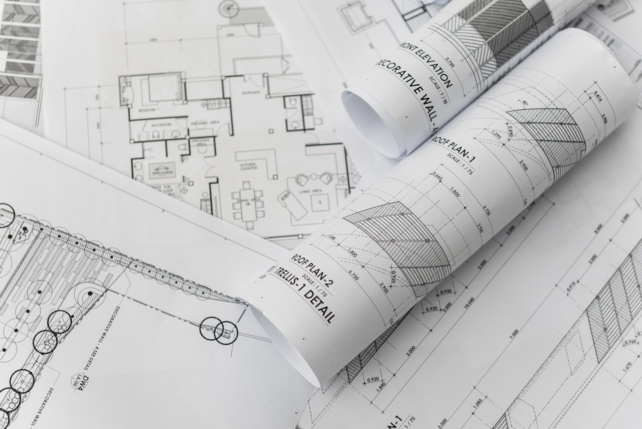
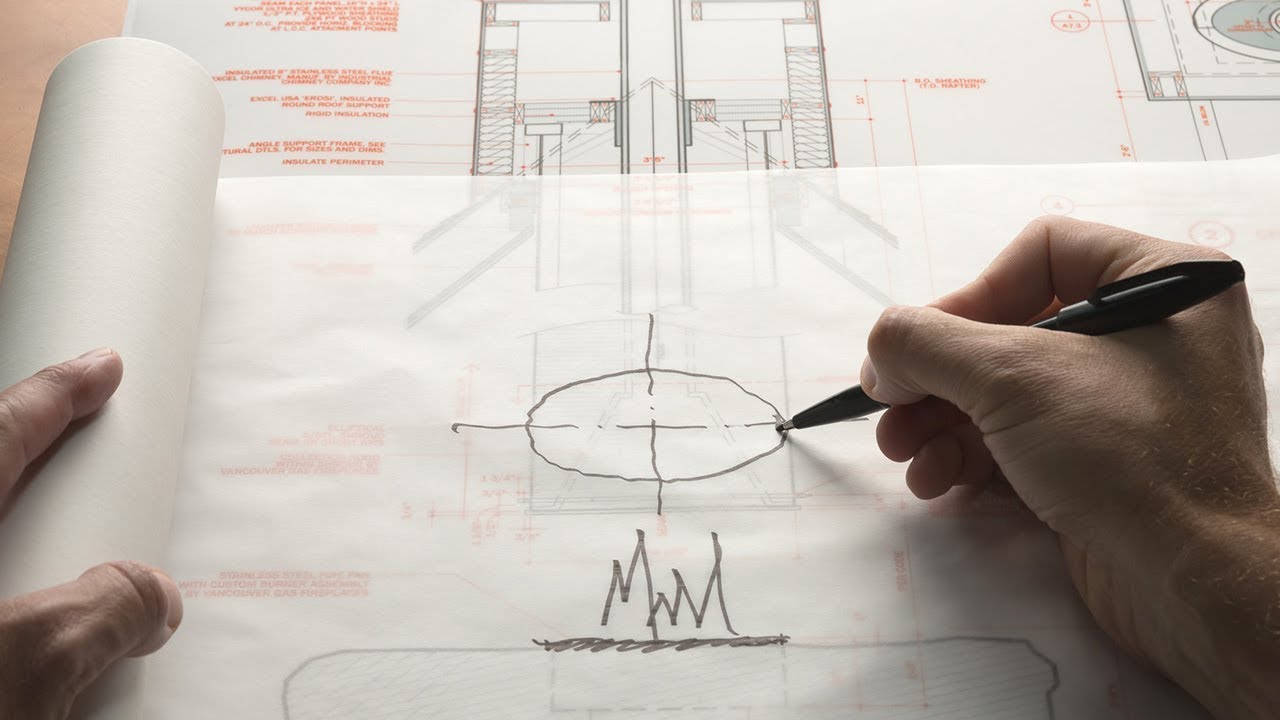
In the world of construction, accurate and detailed drawings are essential for ensuring successful project completion. These drawings serve as a blueprint, providing construction teams with the necessary information to bring a design concept to life. There are various types of construction drawings, each playing a crucial role in guiding the construction process. In this article, we will explore the six main types of construction drawings and their importance in the construction industry.
Construction drawings are technical illustrations that communicate important information about a building’s design, dimensions, materials, and construction methods. They act as a visual representation of the architect’s vision, allowing contractors, engineers, and other professionals involved in the project to understand and implement the design accurately.
Each type of drawing focuses on a different aspect of the construction process and provides specific details that are vital for the successful execution of the project. Let’s dive into each type of construction drawing and understand its purpose and significance.
Key Takeaways:
- Construction drawings, including architectural, structural, MEP, civil, and landscape drawings, are essential blueprints that guide construction teams, ensuring accurate implementation of design details and compliance with building codes and regulations.
- These drawings serve as a universal language, communicating the vision of architects and engineers to construction teams, facilitating collaboration, and ensuring seamless integration of various building systems and elements.
Read more: What Size Are Construction Drawings
Architectural Drawings
Architectural drawings are the foundation of any construction project. These drawings provide a detailed representation of a building’s design and layout. They communicate the architect’s vision and include crucial information about the structure’s dimensions, materials, and finishes. Here are the main types of architectural drawings:
1. Site Plans: Site plans depict the entire project site, including the building, surrounding landscape, parking areas, and any other relevant features. They provide an overview of how the structure is situated on the site, such as its orientation and relationship to neighboring buildings or landmarks.
2. Floor Plans: Floor plans showcase each level of the building from a top-down perspective. They illustrate the layout of rooms, corridors, doorways, windows, and other architectural elements. Floor plans are crucial for understanding the flow and functionality of a building, enabling contractors to accurately construct each space.
3. Elevations: Elevations are two-dimensional drawings that provide a view of the building’s exterior facades, showcasing its appearance from different angles. These drawings highlight the architectural details, such as window placements, material finishes, and decorative elements. Elevations help contractors understand the building’s aesthetic design and ensure accurate construction of its exterior features.
4. Sections: Sections are vertical or horizontal cut-through views of the building. They allow a closer look at the internal structure, showcasing the relationship between different floors and elements like walls, columns, and beams. Sections provide crucial information for contractors to understand the building’s structural components and ensure proper construction.
5. Details: Construction details are drawings that focus on specific elements or sections of the building, providing more in-depth information. These drawings showcase the exact dimensions, materials, and construction methods for features such as windows, doors, staircases, and roof elements. Details ensure precision in the execution of these critical architectural elements.
Architectural drawings are the starting point for any construction project. They serve as a guide for contractors, engineers, and other professionals involved in the building process. These drawings help ensure that the project is constructed according to the architect’s vision, with attention to design details and adherence to building codes and regulations.
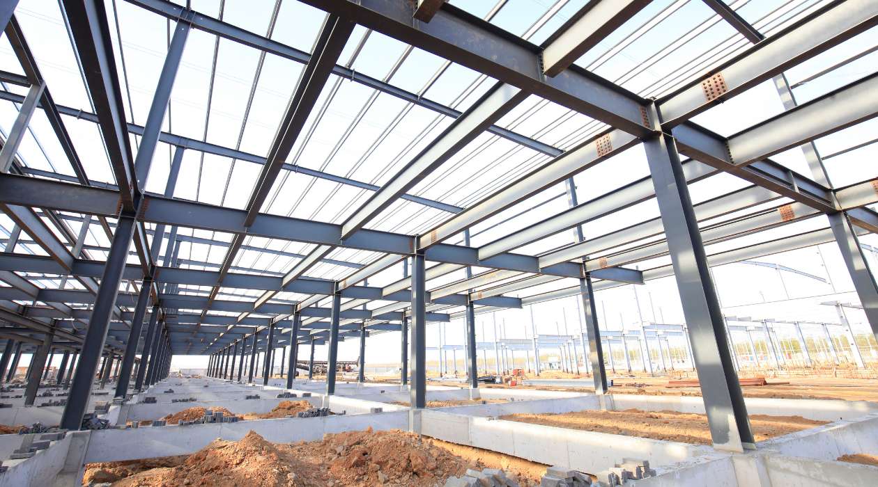
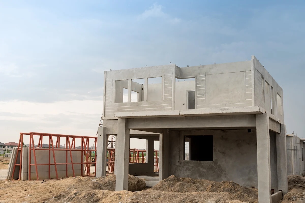
Structural Drawings
Structural drawings are a vital component of any construction project, providing detailed information about the building’s structural integrity and stability. These drawings are essential for architects, engineers, and contractors to ensure that the structure can withstand the loads and forces it will encounter. Here are some key types of structural drawings:
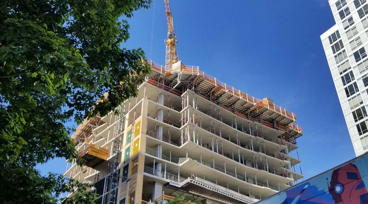
1. Foundation Plans: Foundation plans depict the layout and dimensions of the building’s foundation. They provide crucial information on the type of foundation, such as slab, crawl space, or basement, as well as the locations of footings, piers, and other support elements. Foundation plans ensure that the building has a solid base and can withstand the weight and forces exerted upon it.
2. Framing Plans: Framing plans showcase the structural framework of the building, including walls, columns, beams, and roof trusses. These drawings specify the size, spacing, and connections of the structural elements. Framing plans are essential for ensuring that the building’s structure can support the intended loads and provide stability.
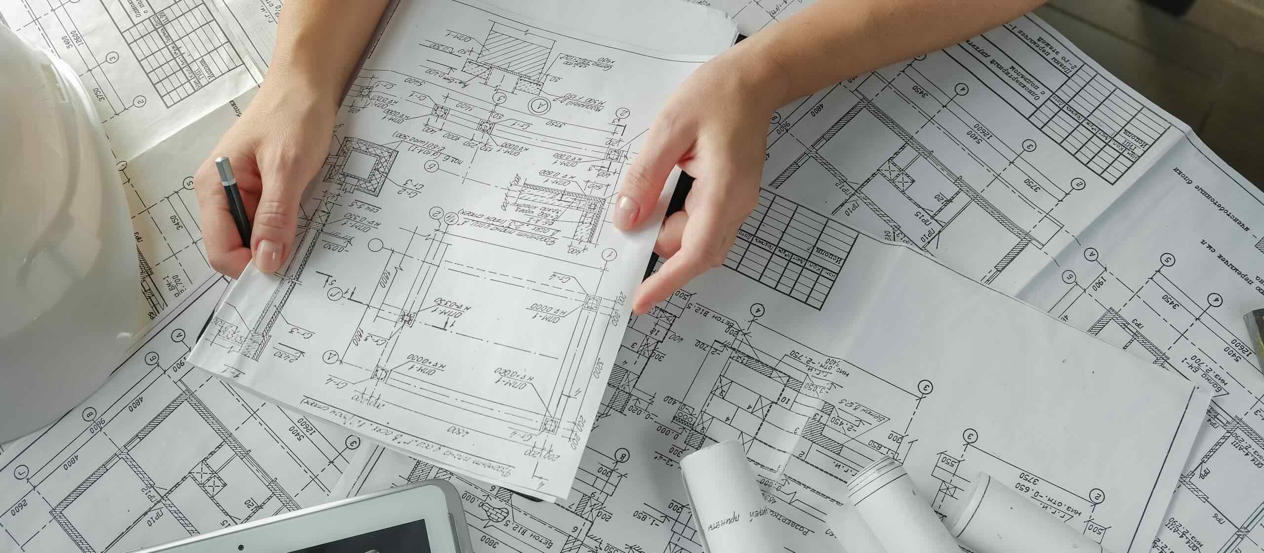
3. Structural Details: Structural details drawings provide specific information about the connections, joints, and reinforcement of the structural components. These detailed drawings ensure that the building’s structural elements are properly connected and reinforced to withstand stress and distribute loads effectively.
4. Structural Calculations: Although not technically drawings, structural calculations accompany the structural drawings. They involve complex engineering calculations to determine the required sizes and strengths of structural elements, such as beams and columns. Structural calculations are crucial for ensuring that the building meets safety standards and can withstand the anticipated loads and forces.
5. Load Calculations: Load calculations determine the anticipated live loads, dead loads, and other forces that the structure will experience. These calculations take into account factors such as occupancy type, materials used, and local building codes. Load calculations are essential for designing the structure’s foundation and framing to support the expected loads appropriately.
Structural drawings provide critical information to construction teams, ensuring the structural integrity and safety of the building. They help professionals understand how the building’s various components fit together and provide guidelines for proper construction techniques. With accurate and detailed structural drawings, contractors can confidently build a safe and durable structure that meets all necessary structural requirements.
MEP (Mechanical, Electrical, Plumbing) Drawings
MEP drawings are an integral part of the construction process, focusing on the mechanical, electrical, and plumbing systems of a building. These drawings provide detailed information about the installation and layout of these essential systems. MEP drawings ensure that the building functions efficiently, providing comfort, safety, and functionality to its occupants. Here are the main types of MEP drawings:
1. Mechanical Drawings: Mechanical drawings depict the HVAC (Heating, Ventilation, and Air Conditioning) systems of the building. These drawings include detailed information about the placement of equipment, such as air handling units, ductwork, and exhaust fans. Mechanical drawings also specify the sizes and capacities of equipment and provide guidelines for duct routing and ventilation design.
2. Electrical Drawings: Electrical drawings focus on the building’s electrical systems, including power distribution, lighting, and communication systems. These drawings specify the locations of electrical panels, outlets, switches, and fixtures, as well as the routing of electrical conduits. Electrical drawings also include information about the capacity and types of wiring, circuit breaker panels, and emergency power systems.
3. Plumbing Drawings: Plumbing drawings illustrate the building’s plumbing systems, including supply lines, drainage systems, and fixtures. These drawings specify the locations of water supply lines, pipes, valves, and plumbing fixtures such as sinks, toilets, and showers. Plumbing drawings also address the layout of sanitary drainage systems, waste disposal, and stormwater drainage.
4. Fire Protection Drawings: Fire protection drawings focus on the installation of fire safety systems within the building. These drawings specify the locations of fire extinguishers, fire alarm systems, sprinkler systems, and emergency exits. Fire protection drawings play a crucial role in ensuring the safety of occupants and compliance with fire codes and regulations.
MEP drawings are essential for coordinating the various systems within a building. They provide critical information for contractors, engineers, and tradespeople to install and connect the mechanical, electrical, and plumbing components accurately. These drawings help ensure that the building’s systems operate efficiently, minimize resource usage, and comply with safety standards and building codes.
When reviewing construction drawings, pay close attention to the architectural, structural, mechanical, electrical, plumbing, and civil drawings to ensure a comprehensive understanding of the project.
Civil Drawings
Civil drawings are a vital part of the construction process, focusing on the site development and infrastructure of a building project. These drawings provide detailed information about the site’s layout, grading, utilities, and other civil engineering aspects. Civil drawings are crucial for ensuring the proper functioning and integration of the building within its surrounding environment. Here are the main types of civil drawings:
1. Site Plan: The site plan is a comprehensive drawing that showcases the entire project site. It includes information about the building’s location, access points, parking areas, landscaping, and other features on the site. Site plans provide an overview of how the building fits within the larger context, including any surrounding infrastructure or natural elements.
2. Grading Plan: Grading plans depict the elevation changes and contours of the site. These drawings illustrate how the land will be modified to accommodate the building and its surroundings. Grading plans specify the slopes, drainage patterns, and earthwork required to shape the site, ensuring proper water flow and stability.
3. Utility Plans: Utility plans include detailed layouts of the site’s underground utilities, such as water supply lines, sewer lines, storm drains, and electrical conduits. These drawings specify the locations, sizes, and connections of these utilities, ensuring that they are properly integrated within the site and can function effectively.
4. Road and Parking Lot Design: Civil drawings also include the design and layout of roads, driveways, and parking areas. These drawings specify the dimensions, paving materials, and traffic flow patterns. Road and parking lot designs consider factors such as vehicle circulation, safety, and accessibility for pedestrians and those with mobility impairments.
5. Retaining Wall and Erosion Control Plans: If the site requires retaining walls or erosion control measures, civil drawings provide the necessary details. These drawings specify the design and construction of retaining walls, addressing factors such as height, materials, and stability. Erosion control plans focus on measures such as slopes, vegetation, and stormwater management to prevent soil erosion and environmental damage.
Civil drawings are essential for coordinating the construction of the building within its site. They enable contractors, engineers, and other professionals to understand and implement the necessary site modifications and infrastructure requirements. These drawings help ensure that the building is harmoniously integrated into its environment, with appropriate access, utilities, and environmental considerations in place.
Read more: What Is A Shop Drawing In Construction
Landscape Drawings
Landscape drawings play a crucial role in enhancing the aesthetics and functionality of a building’s surroundings. These drawings focus on the design and layout of outdoor spaces, including gardens, walkways, outdoor recreational areas, and hardscape features. Landscape drawings ensure the integration of natural elements and provide an inviting and harmonious environment for building occupants and visitors. Here are the main types of landscape drawings:
1. Landscape Plans: Landscape plans are comprehensive drawings that showcase the overall design of the outdoor spaces surrounding the building. They include information about the layout of gardens, lawns, trees, shrubs, and other vegetation. Landscape plans specify the locations of different plant varieties, pathways, seating areas, and focal points, creating an attractive and functional outdoor environment.
2. Planting Plans: Planting plans provide detailed information about the types and locations of plants within the landscape design. These drawings indicate where specific plants, trees, or shrubs should be planted, ensuring proper spacing, sunlight exposure, and aesthetic arrangements. Planting plans consider factors such as seasonal variations, color schemes, and plant maintenance requirements.
3. Hardscape Plans: Hardscape plans focus on the design and placement of non-plant elements within the outdoor space. This includes walkways, patios, outdoor seating areas, water features, and other structures. Hardscape plans consider factors such as materials, dimensions, and accessibility to create functional and visually appealing outdoor spaces.
4. Lighting Plans: Lighting plans incorporate the design and placement of outdoor lighting fixtures. These drawings specify the locations of lights, such as pathway lights, accent lights, and floodlights, to enhance safety, visibility, and ambiance during the evening hours. Lighting plans consider functionality, energy efficiency, and aesthetic effects.
5. Irrigation Plans: Irrigation plans provide details on the water distribution system for the landscape. These drawings specify the location and type of irrigation devices, such as sprinklers or drip lines, to ensure proper hydration of plants and efficient water usage. Irrigation plans consider factors such as water source, water pressure, and zoning for effective irrigation management.
Landscape drawings contribute to the overall appeal and functionality of a building’s external environment. They help transform outdoor spaces into inviting areas for relaxation, recreation, and connection with nature. By incorporating natural and man-made elements, landscape drawings enhance the aesthetic value of the building while promoting sustainability, biodiversity, and a positive outdoor experience for building occupants and visitors.
Conclusion
Construction drawings are a fundamental component in the building industry, providing invaluable information for the successful execution of construction projects. From architectural drawings to structural, MEP, civil, and landscape drawings, each type plays a significant role in guiding construction teams and ensuring the accuracy, functionality, and aesthetics of the final structure.
Architectural drawings provide a visual representation of the building design, guiding contractors in constructing the physical dimensions, layout, and details of the structure. Structural drawings ensure the strength and stability of the building, outlining the foundation, framework, and necessary reinforcements. MEP drawings focus on the mechanical, electrical, and plumbing systems, ensuring buildings are equipped with efficient and functional utilities. Civil drawings address site development and integration, considering grading, utilities, roads, and parking areas. Lastly, landscape drawings enhance the outdoor environment, creating appealing and sustainable spaces around the building.
These drawings act as a universal language that communicates the vision of architects and engineers to the construction team, enabling precise implementation and minimizing errors. They facilitate collaboration and coordination among different professionals involved in the construction process, ensuring seamless integration of various systems and elements of the building.
Moreover, construction drawings are not only crucial during the construction phase but also serve as valuable references for maintenance, renovations, and future modifications. They provide a comprehensive record of the building’s design and infrastructure, aiding in future decision-making and alterations.
In conclusion, construction drawings are indispensable tools that lay the foundation for successful construction projects. They provide a vital link between design and construction, offering precise instructions, specifications, and details that contribute to the overall quality, safety, and functionality of the built environment. From the initial architectural concept to the final landscape details, each type of drawing contributes towards creating remarkable buildings that fulfill the vision and requirements of clients and enhance the communities in which they exist.
Frequently Asked Questions about What Are The 6 Types Of Construction Drawings
Was this page helpful?
At Storables.com, we guarantee accurate and reliable information. Our content, validated by Expert Board Contributors, is crafted following stringent Editorial Policies. We're committed to providing you with well-researched, expert-backed insights for all your informational needs.


0 thoughts on “What Are The 6 Types Of Construction Drawings”