Home>diy>Building & Construction>How To Read Construction Drawings
Building & Construction
How To Read Construction Drawings
Modified: October 21, 2024
Learn how to read construction drawings and gain a deeper understanding of building construction with our comprehensive guide. Enhance your knowledge and skills in the industry.
(Many of the links in this article redirect to a specific reviewed product. Your purchase of these products through affiliate links helps to generate commission for Storables.com, at no extra cost. Learn more)
Introduction
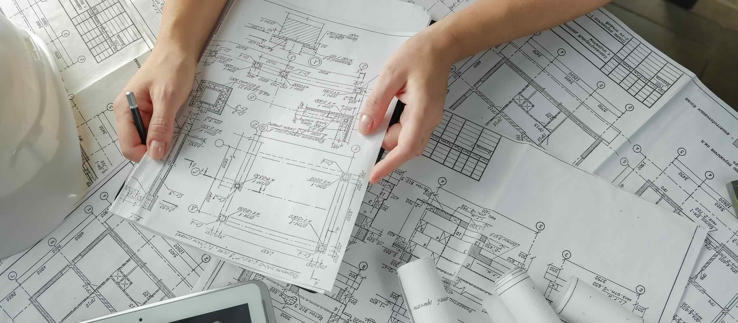
Welcome to the world of construction drawings! These intricate documents are the backbone of any building project, providing a visual roadmap for architects, engineers, contractors, and tradespeople to follow. If you’re new to the field or looking to gain a deeper understanding of construction drawings, you’re in the right place.
Reading construction drawings is an essential skill for anyone involved in the building industry. It allows you to interpret the architect’s vision, understand the structural elements, and coordinate with other trades to ensure a successful and efficient construction process. Whether you’re a contractor, project manager, or aspiring designer, having the ability to read construction drawings will give you a competitive edge and boost your career opportunities.
In this article, we will explore the importance of reading construction drawings and delve into various types of drawings commonly encountered in the construction industry. We will also discuss the symbols and abbreviations used in these drawings, providing you with the tools to decode these documents effectively.
Furthermore, we will take a closer look at reading architectural drawings, which focus on the aesthetic and spatial aspects of the building. We will also explore structural drawings, electrical drawings, plumbing drawings, mechanical drawings, and HVAC drawings, each of which plays a critical role in the successful completion of a construction project.
Throughout this article, we will provide practical tips and insights to help you develop a comprehensive understanding of construction drawings. We will discuss common mistakes to avoid and offer guidance on how to navigate through complex drawings easily. By the end of this article, you will be well-equipped to read and interpret construction drawings with confidence.
So, grab your hard hat, sharpen your pencils, and let’s dive into the fascinating world of construction drawings!
Key Takeaways:
- Understanding construction drawings is crucial for architects, contractors, and tradespeople to interpret design intent, coordinate effectively, estimate costs accurately, ensure code compliance, and execute projects efficiently.
- Avoid common mistakes when reading construction drawings by reviewing the entire set, paying attention to scale and dimensions, consulting key legends, collaborating with stakeholders, and staying updated with revisions.
Read more: How To Read A CAD Drawing
Importance of Reading Construction Drawings
Reading construction drawings is an essential skill for individuals involved in the construction industry. These drawings serve as a visual representation of the architect’s vision and provide crucial information to guide the construction process. Let’s explore the importance of reading construction drawings in more detail:
- Understanding the Design: Construction drawings offer a comprehensive overview of the building’s design. They include details about the layout, dimensions, materials, and finishes, allowing contractors and tradespeople to get a clear picture of what needs to be executed. Without a thorough understanding of the drawings, it becomes difficult to accurately interpret the design intent and deliver a project that meets the architect’s vision.
- Coordination and Collaboration: Construction projects involve multiple trades and disciplines working together. Reading construction drawings enables each trade to understand their specific scope of work and how it interacts with other trades. It facilitates effective coordination and collaboration between architects, engineers, contractors, plumbers, electricians, and other professionals involved in the project.
- Budgeting and Cost Estimation: Construction drawings provide vital information for estimating project costs. By analyzing the drawings, contractors can determine the quantity and type of materials required, as well as the complexity of the work involved. This knowledge is crucial for generating accurate cost estimates, which are essential for bidding on projects and managing budgets throughout the construction process.
- Ensuring Code Compliance: Construction drawings often incorporate building codes and regulations, ensuring that the structure meets safety and regulatory standards. Understanding these drawings allows contractors and tradespeople to identify any potential code violations and make the necessary corrections during the construction phase, avoiding costly rework and ensuring the building’s compliance with local building codes.
- Efficient Project Execution: Reading construction drawings enhances project efficiency. With a clear understanding of the drawings, contractors can plan logistics, schedule tasks, and allocate resources effectively. This results in streamlined construction workflows, reducing delays, minimizing errors, and improving overall project timelines.
In summary, reading construction drawings is vital for architects, contractors, and tradespeople to understand the design intent, coordinate with other professionals, estimate project costs, ensure code compliance, and execute construction projects efficiently. By developing this skill, individuals can enhance their professional capabilities and contribute to the successful completion of construction projects.
Different Types of Construction Drawings
Construction projects involve a wide range of disciplines, each with its own set of requirements and specifications. To effectively communicate the various aspects of a building project, different types of construction drawings are used. Let’s explore some of the most common types of construction drawings:
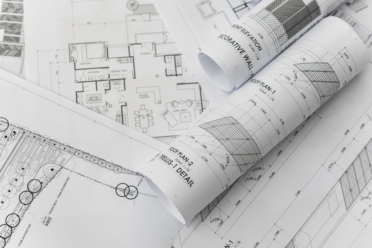
- Architectural Drawings: These drawings provide a visual representation of the building’s design, including floor plans, elevations, sections, and details. They showcase the aesthetic aspects of the project, such as the layout of rooms, placement of doors and windows, and the overall appearance of the structure.
- Structural Drawings: Structural drawings focus on the building’s structural elements and the forces acting upon them. They include details about the foundation, columns, beams, walls, and other load-bearing components. Structural drawings are essential for ensuring the structural integrity of the building and coordinating with the engineering team.
- Electrical Drawings: Electrical drawings depict the electrical layout of the building, including the placement of outlets, switches, lighting fixtures, and electrical panels. These drawings also include information about wiring diagrams, circuitry, and load calculations. Electricians rely on these drawings to ensure safe and efficient electrical installations.
- Plumbing Drawings: Plumbing drawings provide details about the building’s plumbing system, including the location of pipes, fixtures, valves, and drains. They illustrate how water supply and drainage systems are connected and help plumbers understand the plumbing layout for installation, maintenance, and repairs.
- Mechanical Drawings: Mechanical drawings focus on the mechanical systems of the building, such as heating, ventilation, and air conditioning (HVAC) systems. These drawings show the placement of HVAC equipment, air ducts, and pipes, as well as control systems. Mechanical drawings are critical for HVAC technicians to ensure proper installation and functioning of these systems.
- HVAC Drawings: HVAC drawings specifically focus on the heating, ventilation, and air conditioning systems. They provide detailed information on ductwork, diffusers, grilles, and other components related to HVAC system installation. HVAC drawings enable HVAC contractors to design, install, and maintain efficient heating and cooling systems.
These are just a few examples of the types of construction drawings you may encounter in the industry. Each type serves a specific purpose and provides valuable information to various professionals involved in the construction process. Understanding these drawings is crucial for effective coordination, accurate installations, and ensuring the successful completion of building projects.
Understanding the Symbols and Abbreviations
Construction drawings rely heavily on symbols and abbreviations to convey information quickly and efficiently. These graphical representations and shorthand notations help streamline the communication process and make the drawings more accessible to professionals in the industry. Let’s dive into the importance of understanding symbols and abbreviations in construction drawings:
Symbols:
Construction drawings use a vast array of symbols to represent various elements, components, and materials. These symbols serve as visual shortcuts, allowing readers to quickly identify and interpret specific features without the need for lengthy explanations. For example, a circle with a cross inside may represent an electrical outlet, while a triangle may denote a steel column. It is crucial to familiarize yourself with commonly used symbols in the specific discipline you are working in to ensure accurate interpretation of the drawings.
Abbreviations:
Abbreviations are used to condense information and make drawings more concise. They are often employed for measurements, materials, equipment, and construction techniques. Common abbreviations include “CAD” for Computer-Aided Design, “HVAC” for Heating, Ventilation, and Air Conditioning, and “DWG” for Drawing. Understanding these abbreviations is essential to comprehend the information presented in construction drawings accurately.
Key Legends and References:
Many construction drawings include a key legend or reference section that provides an explanation of the symbols and abbreviations used. This section acts as a guide, helping readers understand the different symbols and their corresponding meanings. Always refer to the key legend whenever you encounter unfamiliar symbols or abbreviations to ensure accurate interpretation of the drawings.
Scale:
One crucial aspect of understanding construction drawings is the scale. The scale indicates the ratio between the measurements on the drawing and the actual dimensions of the building. It allows readers to visualize the size and proportions of the elements accurately. Common scales include 1/8″ = 1 foot or 1:100. Pay close attention to the scale indicated on the drawings to ensure precise measurements and accurate understanding of the project.
Trade-Specific Symbols and Abbreviations:
Keep in mind that symbols and abbreviations may vary depending on the specific trade or discipline. For example, electrical drawings will use symbols specific to electrical components, while plumbing drawings will use symbols related to pipes and fixtures. It’s crucial to familiarize yourself with the symbols and abbreviations specific to your field of expertise to ensure accurate interpretation of the drawings.
Understanding the symbols and abbreviations used in construction drawings is vital for accurate interpretation and effective communication. Taking the time to learn and familiarize yourself with common symbols and abbreviations will help you navigate through the drawings with confidence, ensuring successful project coordination and execution.
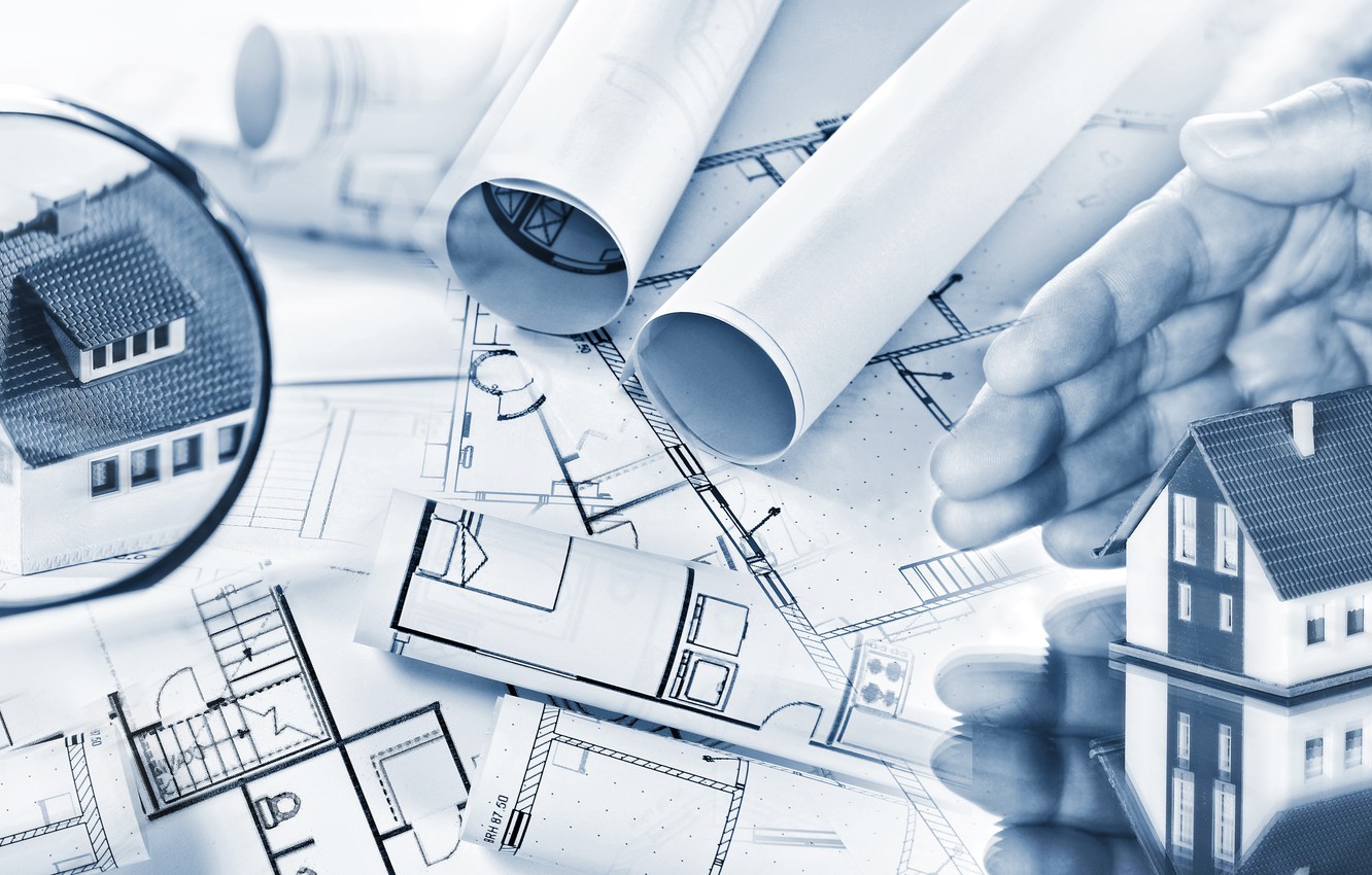
Reading Architectural Drawings
Architectural drawings are the visual representation of a building’s design and serve as a blueprint for construction. To effectively navigate architectural drawings, it is essential to understand the various elements and symbols used. Here are some key aspects to consider when reading architectural drawings:
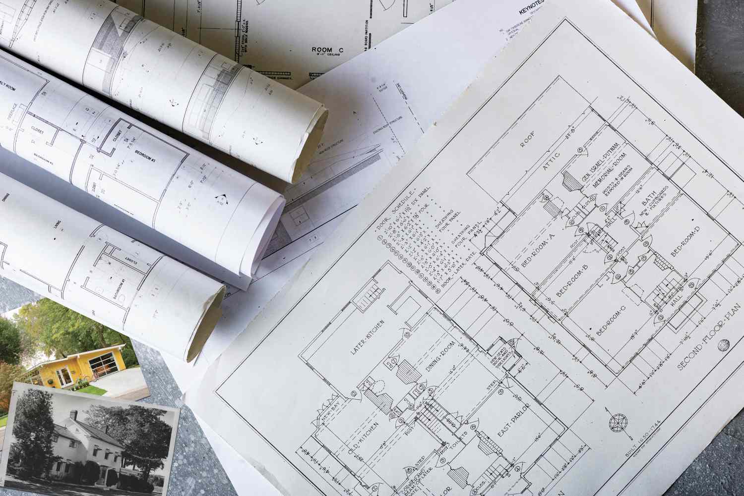
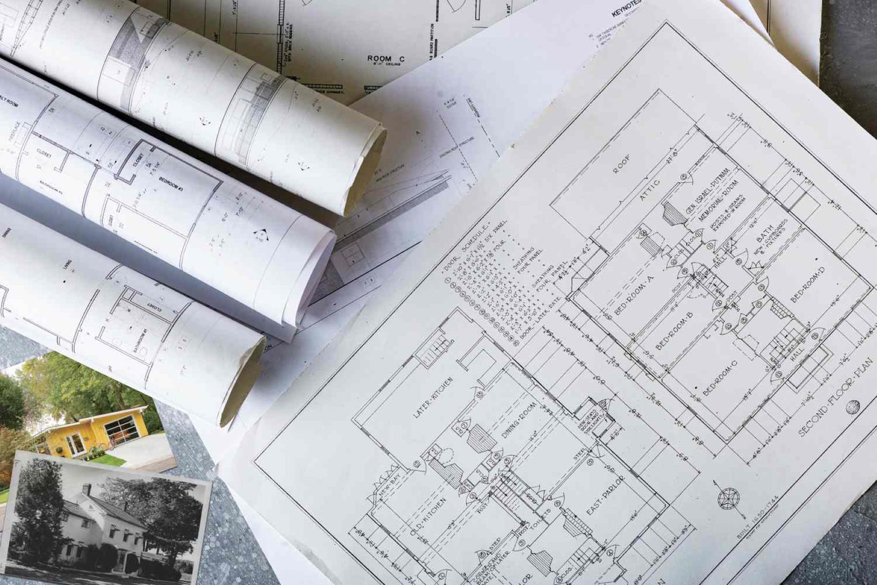
Floor Plans:
Floor plans are the most common and foundational component of architectural drawings. They provide a top-down view of each level of the building, illustrating the layout of rooms, walls, doors, and windows. Floor plans also show dimensions and may include symbols to indicate the function of each space (e.g., bedrooms, bathrooms, kitchen). By studying the floor plans, you can gain a comprehensive understanding of the spatial arrangement and flow of the building.
Elevations:
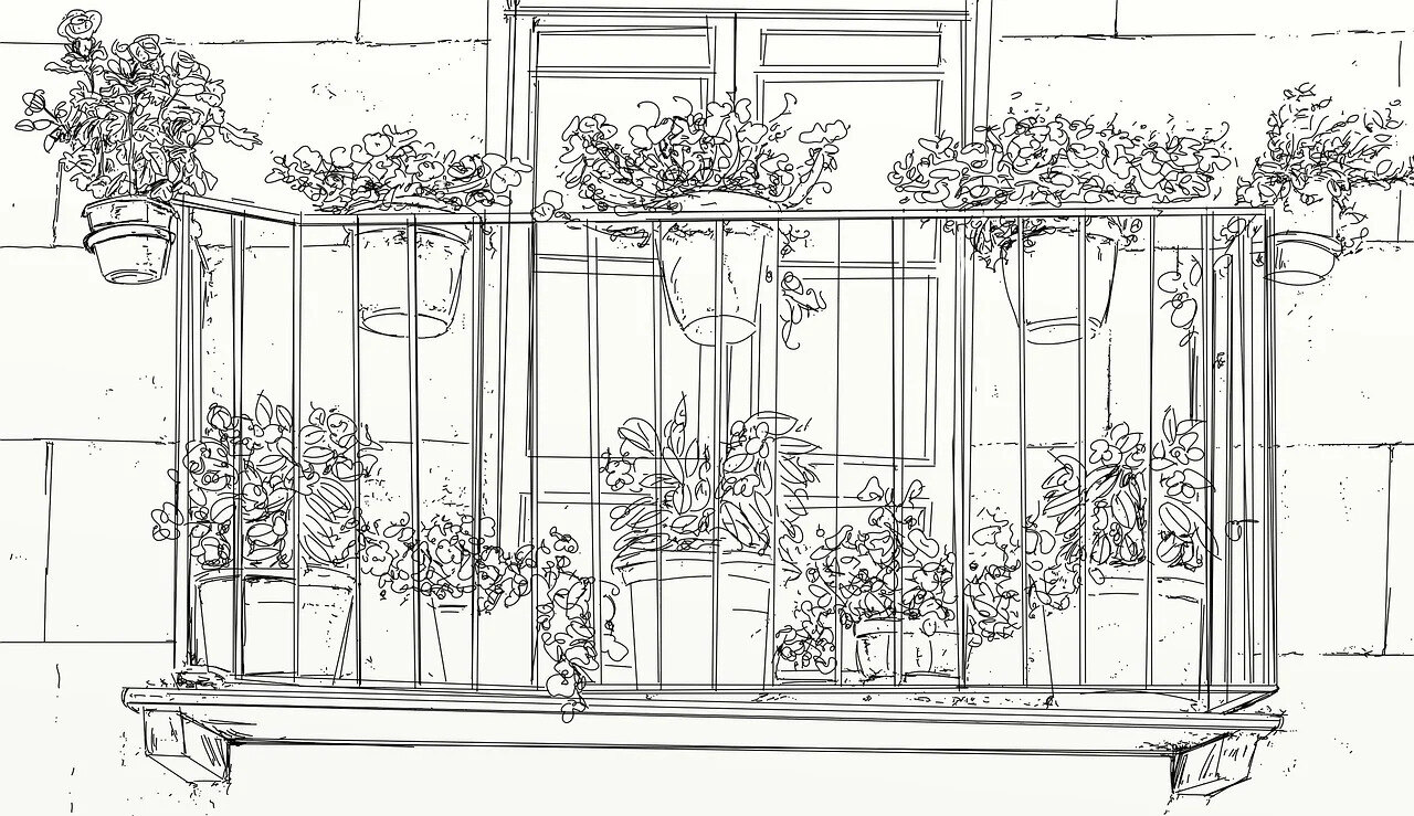
Elevations are external views of the building, showing its appearance from different angles. These drawings provide a three-dimensional representation of the building’s exterior. Elevations include details such as the height and width of the building, location of windows and doors, and architectural features like columns or balconies. Analyzing elevations aids in understanding the building’s aesthetic design and how it will integrate into its surroundings.
Sections:
Sections are vertical cutaways of the building, showing internal details in a cross-sectional view. They reveal important information about the height and shape of ceilings, the arrangement of structural elements, and the relationship between different building systems. Sections allow you to understand the internal structure and how different building components come together.
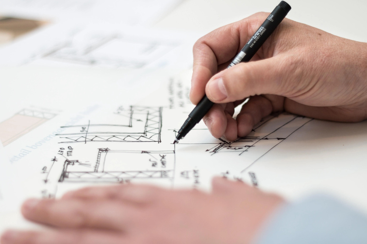
Details:
Architectural drawings include detailed drawings that focus on specific building elements, such as doors, windows, stairs, or wall sections. These drawings provide close-up views and specific dimensions, ensuring accurate construction and detailing of these elements. Paying attention to these details helps ensure precision in building execution.
Symbols and Annotations:
Architectural drawings use various symbols and annotations to convey information efficiently. Symbols may represent different materials, fixtures, or equipment. Annotations provide additional information and clarify specific details. It is essential to refer to the key legend or reference section of the drawings to understand the meaning of symbols and annotations correctly.
Scale and Dimensions:
Architectural drawings are drawn to scale, indicating the ratio between the drawing and the actual building dimensions. Paying attention to the scale ensures accurate measurement and understanding of the spaces depicted. Additionally, dimensions are provided to indicate the exact sizes of rooms, openings, and other elements, allowing for precise construction.
Reading architectural drawings requires careful observation, attention to detail, and an understanding of the various components and symbols used. By immersing yourself in the floor plans, elevations, sections, and details, you will grasp the architect’s design intent and be able to effectively communicate and collaborate with the construction team.
Read more: How To Become A Construction Draw Inspector
Reading Structural Drawings
Structural drawings play a crucial role in the construction process by providing detailed information about a building’s structural elements and ensuring its stability and safety. As a key component of the construction drawings, understanding structural drawings is essential for contractors, engineers, and tradespeople. Here are some important aspects to consider when reading structural drawings:
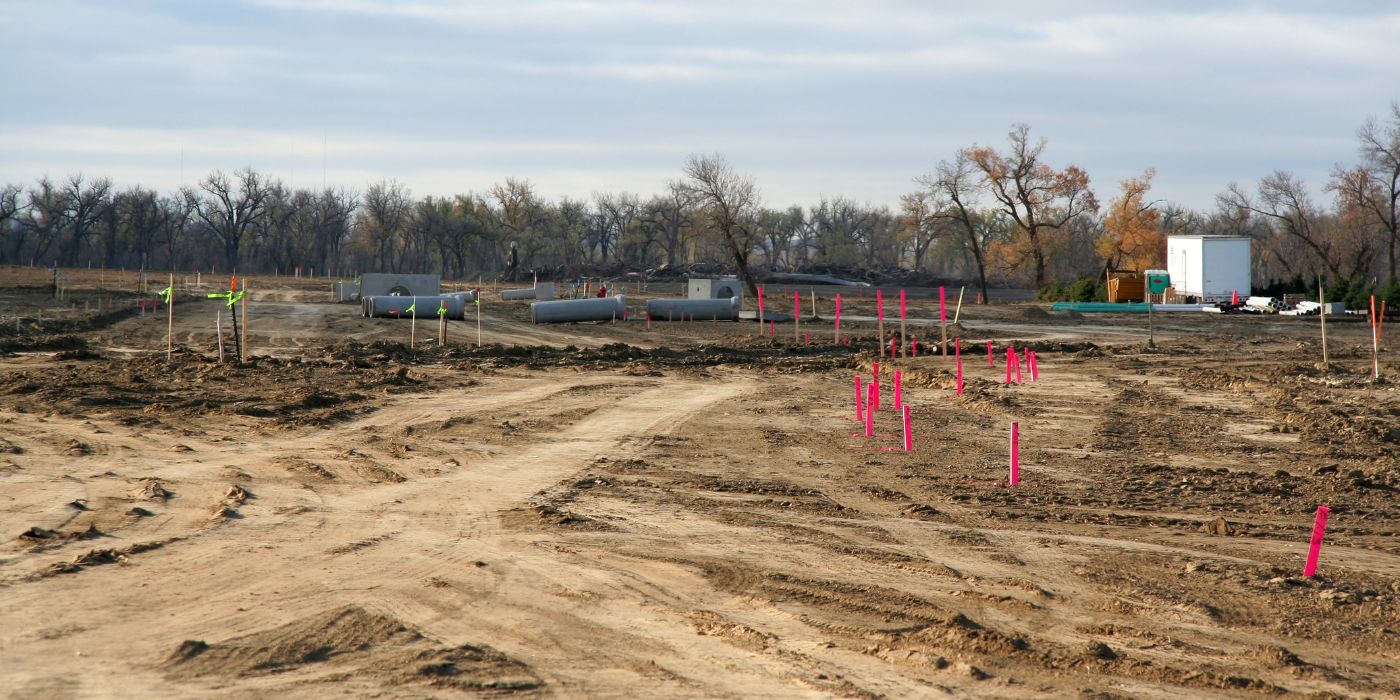
Foundation Plans:
Foundation plans provide an overview of the building’s foundation system. These drawings depict the dimensions, layout, and type of foundation, whether it’s a concrete slab, crawl space, or basement. Foundation plans also indicate the location of footings, columns, and support walls. Understanding foundation plans is crucial for ensuring a solid and stable base for the entire structure.
Structural Framing Plans and Layouts:
The structural framing plans provide details about the building’s framework, including columns, beams, girders, and joists. These drawings outline the sizes, locations, and connections of these structural elements. The framing plans also show the arrangement of floor and roof systems. Understanding the structural framing plans is essential for proper installation and coordination with other building systems.
Sections and Details:
Sections and details in structural drawings provide a closer look at specific parts of the building’s structure. Sections illustrate vertical or horizontal slices of the building, showcasing critical elements such as load-bearing walls, structural connections, and the relationship between different floors. Detailed drawings focus on specific structural features, such as connections, reinforcements, or bracing requirements. These drawings help ensure accurate construction and compliance with engineering specifications.
Beam and Column Schedules:
Beam and column schedules provide a comprehensive list of all beams and columns in the building. These schedules typically include information about the dimensions, material specifications, and the location of each beam and column. The schedules assist in accurately ordering and installing the necessary structural components.
Structural Symbols and Annotations:
Structural drawings use various symbols and annotations to convey important information effectively. Symbols may represent different types of structural elements or connections, while annotations provide additional details or clarifications. It’s crucial to refer to the key legend or reference section to understand the meaning of symbols and annotations precisely.
Load and Design Calculations:
Structural drawings may also include load and design calculations, which provide important information about the magnitude and distribution of loads that the structure must support. These calculations assist engineers and contractors in ensuring the structural integrity and adequacy of the building.
When reading structural drawings, attention to detail, knowledge of structural terminology, and understanding engineering principles are critical. Collaboration and coordination with structural engineers and other professionals involved in the project is essential to ensure accurate interpretation and implementation of the structural drawings. By grasping the information conveyed in the structural drawings, you can contribute to the safe and successful construction of the building.
When reading construction drawings, start by familiarizing yourself with the symbols and abbreviations used in the drawings to understand the different elements and dimensions.
Reading Electrical Drawings
Electrical drawings are an integral part of construction plans, providing detailed information about the electrical systems within a building. These drawings are crucial for electricians, contractors, and other professionals involved in the electrical installation process. Here are key aspects to consider when reading electrical drawings:
Electrical Layout:
The electrical layout is an essential part of electrical drawings as it provides an overview of the building’s electrical system. It includes the placement and arrangement of outlets, switches, lighting fixtures, panels, and other electrical components. By studying the electrical layout, electricians can visualize the electrical circuitry and plan the installation process efficiently.
Wiring Diagrams:
Wiring diagrams present the electrical connections and routes of the wiring throughout the building. They specify the conductor sizes, colors, and types. Wiring diagrams are essential for understanding how individual components and systems are interconnected. They also help in troubleshooting electrical problems and ensuring proper installation.
Symbol Identification:
Electrical drawings use specific symbols to represent different electrical components and devices. It is crucial to familiarize yourself with these symbols to understand the drawing accurately. Common symbols include those for switches, outlets, lights, transformers, and circuit breakers. Referring to the key legend or reference section of the drawings can help identify and decipher these symbols.
Circuit Designations:
Electrical drawings typically include circuit designations to indicate the different electrical circuits within the building. Each circuit is assigned a unique label or number, which can be referenced throughout the drawings. Understanding these designations ensures proper identification and connection of circuits during the installation process.
Load Calculations:
Electrical drawings may include load calculations, which provide details about the expected electrical load on each circuit or panel. This information is crucial for determining the capacity of the electrical system and selecting appropriate wire sizes, breakers, and other electrical equipment.
Single-Line Diagrams:
Single-line diagrams depict the electrical system using simplified symbols and lines to represent the major electrical components and connections. These diagrams provide a clear overview of the entire electrical system, including main panels, sub-panels, transformer connections, and major feeders. Single-line diagrams are valuable for understanding the overall electrical distribution and identifying key components.
Code Compliance:
Electrical drawings incorporate electrical codes and regulations to ensure compliance with safety standards. Familiarize yourself with the local electrical codes and ensure that the electrical drawings adhere to these requirements. Pay attention to details such as conduit sizing, grounding, and clearances to ensure a safe and code-compliant electrical installation.
Reading electrical drawings requires knowledge of electrical symbols, wiring diagrams, circuit designations, and load calculations. Collaboration with electrical engineers and contractors is crucial to accurately interpret and implement the information presented in the drawings. By understanding electrical drawings, you can ensure a safe and efficient electrical installation within the building.
Reading Plumbing Drawings
Plumbing drawings are essential in any construction project, providing detailed information about the plumbing systems within a building. These drawings are crucial for plumbers, contractors, and other professionals involved in the plumbing installation process. Here are key aspects to consider when reading plumbing drawings:
Plumbing Layout:
The plumbing layout provides an overview of the building’s plumbing system. It includes the placement and arrangement of pipes, fixtures, valves, and other plumbing components. By studying the plumbing layout, plumbers can visualize the flow of water and plan the installation process efficiently.
Piping and Drainage Details:
Piping and drainage details show the specific routes and connections of the pipes throughout the building. These drawings indicate the sizes, materials, slopes, and other specifications of the pipes. Proper understanding of piping and drainage details is crucial for correct installation and functionality of the plumbing system.
Symbols Identification:
Plumbing drawings use specific symbols to represent different plumbing fixtures, valves, and fittings. It is essential to familiarize yourself with these symbols to understand the drawing accurately. Common symbols include those for sinks, toilets, showers, water heaters, shut-off valves, and cleanouts. Referring to the key legend or reference section of the drawings can help identify and decipher these symbols.
Hot and Cold Water Supply:
Plumbing drawings indicate the hot and cold water supply lines, including the placement of valves, distribution points, and fixtures. Understanding the layout and design of the hot and cold water supply lines is essential for ensuring proper water flow, temperature regulation, and efficient distribution of water throughout the building.
Drainage and Venting Systems:
Plumbing drawings depict the drainage and venting systems, including the placement of drain pipes, traps, cleanouts, and vents. These drawings provide valuable information on how wastewater is removed from the building and how sewer gases are safely vented. Proper coordination and understanding of the drainage and venting systems are crucial for ensuring a functional and code-compliant plumbing system.
Isometric Drawings:
Isometric drawings provide a three-dimensional representation of the plumbing system, showing the relationship and orientation of pipes and fixtures. These drawings help plumbers visualize complex pipe runs and identify potential conflicts or clashes with other building systems. Isometric drawings aid in accurate installation and coordination with other trades.
Code Compliance:
Plumbing drawings incorporate plumbing codes and regulations to ensure compliance with safety standards. Familiarize yourself with the local plumbing codes and ensure that the plumbing drawings adhere to these requirements. Pay attention to details such as pipe sizing, fixture clearances, and venting requirements to ensure a safe and code-compliant plumbing installation.
Reading plumbing drawings requires knowledge of plumbing symbols, piping details, drainage and venting systems, and code compliance. Collaboration with plumbing engineers and contractors is crucial to accurately interpret and implement the information presented in the drawings. By understanding plumbing drawings, you can ensure a functional and efficient plumbing system within the building.
Reading Mechanical Drawings
Mechanical drawings provide detailed information about the mechanical systems within a building, including heating, ventilation, and air conditioning (HVAC), as well as other mechanical equipment. These drawings are crucial for HVAC technicians, contractors, and other professionals involved in the installation and maintenance of mechanical systems. Here are key aspects to consider when reading mechanical drawings:
HVAC Layout:
The HVAC layout is a fundamental part of mechanical drawings, illustrating the placement and arrangement of HVAC units, ductwork, vents, and other components. It provides an overview of the heating and cooling distribution system within the building. By studying the HVAC layout, HVAC technicians can understand the airflow patterns and plan the installation process accordingly.
Equipment Specifications:
Mechanical drawings include specifications for mechanical equipment, such as chillers, boilers, pumps, and air handling units. These specifications outline the technical details, including sizes, capacities, power requirements, and manufacturers. Understanding the equipment specifications is essential for proper installation, maintenance, and coordination with other building systems.
Ductwork Layout:
Ductwork layout drawings show the routing and configuration of the ducts, which distribute conditioned air throughout the building. These drawings detail the size, dimensions, insulation, and fittings of the ducts. Proper comprehension of the ductwork layout is crucial for accurate installation and efficient distribution of conditioned air.
Symbols Identification:
Mechanical drawings use specific symbols to represent different mechanical equipment, ducts, vents, and control devices. It is essential to familiarize yourself with these symbols to accurately interpret the drawing. Common symbols include those for HVAC units, fans, dampers, thermostats, and control valves. Referring to the key legend or reference section of the drawings can help identify and understand these symbols.
Piping and Plumbing Connections:
Mechanical drawings may include the layout and connections of mechanical piping, such as chilled water lines or hot water supply lines. These drawings show the routing, sizes, and connections of the pipes as they relate to the mechanical equipment. Understanding the piping and plumbing connections is essential for accurate installation and coordination with other trades.
Control Systems:
Mechanical drawings often include details about the control systems used to regulate and monitor the mechanical equipment. These drawings indicate the location of thermostats, sensors, control panels, and wiring diagrams. Understanding the control systems helps HVAC technicians program, troubleshoot, and maintain the mechanical systems effectively.
Code Compliance:
Mechanical drawings incorporate mechanical codes and regulations to ensure compliance with safety standards. Familiarize yourself with the local mechanical codes and ensure that the mechanical drawings adhere to these requirements. Pay attention to details such as duct sizing, air balance, and accessibility to ensure a safe and code-compliant mechanical installation.
Reading mechanical drawings requires knowledge of mechanical symbols, equipment specifications, ductwork layout, and code compliance. Collaboration with mechanical engineers and contractors is crucial to accurately interpret and implement the information presented in the drawings. By understanding mechanical drawings, you can ensure a properly functioning and energy-efficient mechanical system within the building.
Read more: How To Do Construction Drawings
Reading HVAC Drawings
HVAC (Heating, Ventilation, and Air Conditioning) drawings provide detailed information about the HVAC systems within a building, including heating, cooling, ventilation, and air distribution. These drawings play a critical role in the installation and maintenance of HVAC systems and are essential for HVAC technicians, contractors, and other professionals involved in the field. Here are key aspects to consider when reading HVAC drawings:
HVAC Layout:
The HVAC layout is a fundamental part of HVAC drawings, illustrating the placement and arrangement of HVAC units, ductwork, vents, and other components. It provides an overview of the heating and cooling distribution system within the building. By studying the HVAC layout, HVAC technicians can understand the airflow patterns and plan the installation process efficiently.
Symbols Identification:
HVAC drawings use specific symbols to represent different HVAC components and devices. It is essential to familiarize yourself with these symbols to accurately interpret the drawing. Common symbols include those for HVAC units, fans, dampers, thermostats, and control valves. Referring to the key legend or reference section of the drawings can help identify and understand these symbols.
Ductwork Layout:
Ductwork layout drawings show the routing and configuration of the ducts, which distribute conditioned air throughout the building. These drawings detail the size, dimensions, insulation, and fittings of the ducts. Understanding the ductwork layout is crucial for accurate installation and efficient distribution of conditioned air.
Equipment Specifications:
HVAC drawings often include specifications for HVAC equipment, such as air handling units, chillers, boilers, and heat pumps. These specifications outline the technical details, including sizes, capacities, power requirements, and manufacturers. Understanding the equipment specifications is essential for proper installation, maintenance, and coordination with other building systems.
Piping and Plumbing Connections:
HVAC drawings may include the layout and connections of HVAC piping, such as chilled water lines, hot water supply lines, or refrigerant lines. These drawings show the routing, sizes, and connections of the pipes as they relate to the HVAC systems. Understanding the piping and plumbing connections is essential for accurate installation and coordination with other trades.
Control Systems:
HVAC drawings often include details about the control systems used to regulate and monitor the HVAC equipment. These drawings indicate the location of thermostats, sensors, control panels, and wiring diagrams. Understanding the control systems helps HVAC technicians program, troubleshoot, and maintain the HVAC systems effectively.
Code Compliance:
HVAC drawings incorporate HVAC codes and regulations to ensure compliance with safety standards. Familiarize yourself with the local HVAC codes and ensure that the HVAC drawings adhere to these requirements. Pay attention to details such as duct sizing, air balance, ventilation rates, and energy efficiency to ensure a safe and code-compliant HVAC installation.
Reading HVAC drawings requires knowledge of HVAC symbols, equipment specifications, ductwork layout, and code compliance. Collaboration with HVAC engineers and contractors is crucial to accurately interpret and implement the information presented in the drawings. By understanding HVAC drawings, you can ensure a comfortable and energy-efficient HVAC system within a building.
Common Mistakes to Avoid When Reading Construction Drawings
Reading construction drawings can be a complex task that requires attention to detail and careful interpretation. To ensure accurate understanding and smooth project execution, it’s important to be aware of common mistakes that can occur when reading construction drawings. Here are some common mistakes to avoid:
Not Reviewing the Entire Set of Drawings:
One common mistake is not thoroughly reviewing the entire set of construction drawings. It’s essential to examine all the drawings, including architectural, structural, electrical, plumbing, and mechanical, as they often contain interconnected information. Neglecting to review any portion of the drawings can lead to misinterpretation and coordination issues.
Ignoring Scale and Dimensions:
Overlooking the scale and dimensions of the drawings can result in incorrect measurements and inaccurate interpretations. It’s crucial to pay attention to the scale indicated on the drawings and use it as a reference when analyzing dimensions and spatial relationships between elements. Ignoring scale can lead to costly errors during the construction process.
Not Consulting the Key Legend or Reference Section:
Construction drawings often include a key legend or reference section that provides explanations for symbols, abbreviations, and other notations used throughout the drawings. Failing to consult this key legend can lead to misunderstandings and misinterpretations. Always refer to the key legend or reference section to ensure a clear understanding of the symbols and abbreviations.
Not Communicating and Collaborating with Other Stakeholders:
Construction drawings are a collaborative tool that requires communication and coordination among different stakeholders. It’s important to communicate and collaborate with architects, engineers, contractors, and tradespeople to ensure a comprehensive understanding of the drawings. Failing to collaborate effectively can result in conflicts, delays, and errors during the construction process.
Skipping Over Details and Annotations:
Details and annotations provide critical information about specific elements or nuances on the drawings. Skipping over these details can lead to incorrect interpretations and inaccuracy in the construction process. Pay close attention to the details and annotations to ensure a thorough understanding of the drawings.
Not Staying Updated with Revisions:
Construction drawings may undergo revisions and updates throughout the project lifecycle. Failing to stay updated with these revisions can lead to outdated information and confusion among the project team. Regularly check for updates and ensure that all stakeholders have the latest versions of the drawings to avoid costly mistakes.
Not Consulting with Subject Matter Experts:
Construction drawings often require specific knowledge and expertise in various disciplines. It’s important to consult with subject matter experts, such as structural engineers, electricians, or plumbers, when interpreting and implementing the drawings. Relying solely on personal understanding without expert input can lead to incorrect installation, non-compliance with codes, and safety issues.
Avoiding these common mistakes when reading construction drawings will improve accuracy, reduce errors, and enhance collaboration among project stakeholders. By paying attention to details, communicating effectively, and seeking expert guidance, you can ensure successful project execution and the realization of the intended design.
Conclusion
Reading construction drawings is an essential skill for individuals involved in the building industry. These drawings serve as a visual roadmap, guiding the construction process and ensuring the successful completion of a project. Throughout this article, we have explored the importance of reading construction drawings, discussed the different types of drawings, and highlighted the significance of understanding symbols, abbreviations, and scales.
By developing the ability to read and interpret construction drawings, you gain valuable insights into the design, coordination, and implementation of various building systems. Whether you’re reading architectural drawings to understand the spatial layout, deciphering structural drawings to ensure stability, interpreting electrical drawings for safe and efficient installations, comprehending plumbing drawings for functional water supply and drainage, or analyzing mechanical and HVAC drawings to facilitate comfortable and energy-efficient building environments — the skills acquired in reading construction drawings are indispensable.
However, it is important to be aware of common mistakes to avoid, such as not reviewing the entire set of drawings, ignoring scale and dimensions, neglecting to consult key legends or reference sections, and skipping over important details and annotations. Effective communication, collaboration, and staying updated with revisions are also critical elements in successfully reading and implementing construction drawings.
Remember, reading construction drawings is not a solitary task. It requires teamwork and coordination among architects, engineers, contractors, and tradespeople. By fostering open communication and seeking expert input, you can develop a comprehensive understanding of the drawings and ensure accurate execution of the design intent.
So, whether you’re a seasoned professional or just starting your career in the construction industry, investing time and effort in honing your ability to read construction drawings will pay off in countless ways. It will enhance your professional capabilities, improve project coordination, and contribute to the successful and efficient completion of construction projects.
So put on your hard hat, grab your pencil, and dive into the world of construction drawings. With a keen eye for detail and a solid understanding of the symbols, abbreviations, and design intent, you’ll be equipped to navigate the complex world of construction drawings like a seasoned pro.
Frequently Asked Questions about How To Read Construction Drawings
Was this page helpful?
At Storables.com, we guarantee accurate and reliable information. Our content, validated by Expert Board Contributors, is crafted following stringent Editorial Policies. We're committed to providing you with well-researched, expert-backed insights for all your informational needs.


0 thoughts on “How To Read Construction Drawings”