Home>diy>Building & Construction>How To Do Construction Drawings
Building & Construction
How To Do Construction Drawings
Modified: October 20, 2024
Learn how to create detailed construction drawings for building construction projects. Get step-by-step guidance and tips from industry experts.
(Many of the links in this article redirect to a specific reviewed product. Your purchase of these products through affiliate links helps to generate commission for Storables.com, at no extra cost. Learn more)
Introduction
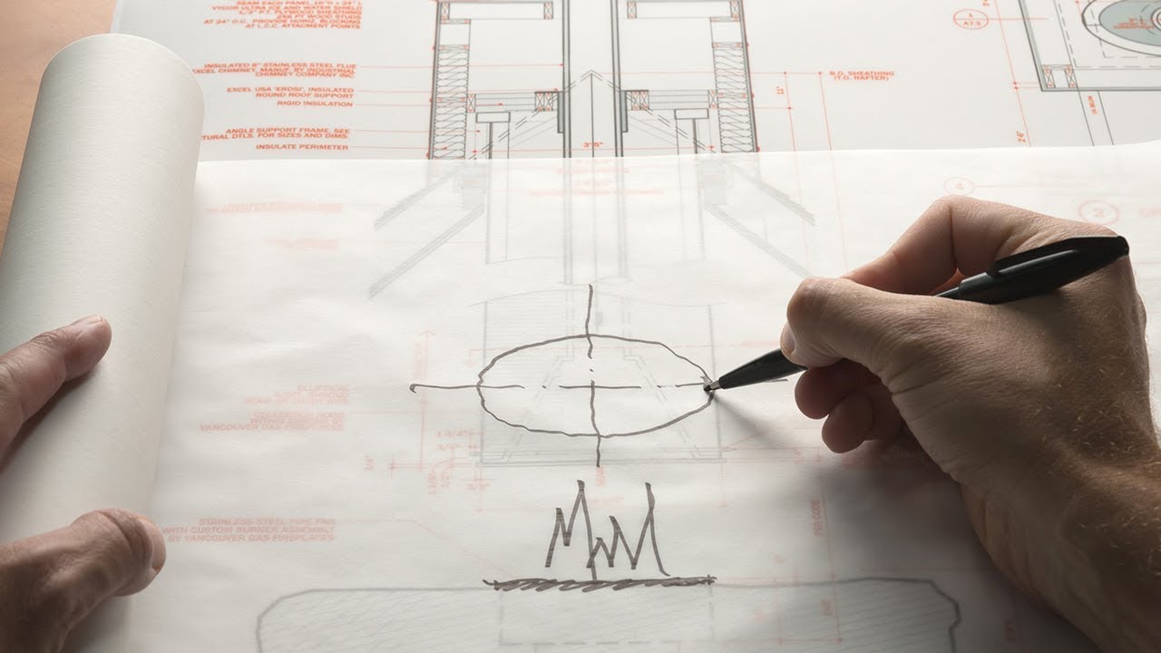
Construction drawings are an integral part of the building process. They serve as a roadmap for architects, engineers, and contractors to follow when constructing a building. These drawings provide detailed information about the design, dimensions, and specifications of various components of a structure.
Whether you’re embarking on a small home renovation project or planning a large-scale commercial construction, understanding how to create construction drawings is essential. In this article, we will guide you through the process of creating accurate and comprehensive construction drawings.
Before we dive into the details, it’s important to note that construction drawings go beyond simple sketches. They are precise and technical documents that help professionals visualize, plan, and execute a construction project. With the right knowledge and tools, you can create clear and concise construction drawings that communicate your design intent effectively.
Key Takeaways:
- Construction drawings are detailed, technical documents that serve as a roadmap for building projects. They require precision, collaboration, and compliance with regulations to ensure successful execution.
- The process of creating construction drawings involves gathering project information, analyzing site conditions, designing floor plans, detailing structural components, and incorporating mechanical, electrical, and plumbing systems. Thorough review and approval are crucial for accuracy and compliance.
Read more: How To Become A Construction Draw Inspector
Understanding Construction Drawings
Construction drawings are a set of graphical and written documents that provide a detailed representation of a building project. These drawings communicate the architectural, structural, electrical, and mechanical aspects of a construction project. They are created by architects, engineers, and drafters to ensure accurate interpretation and execution of the design.
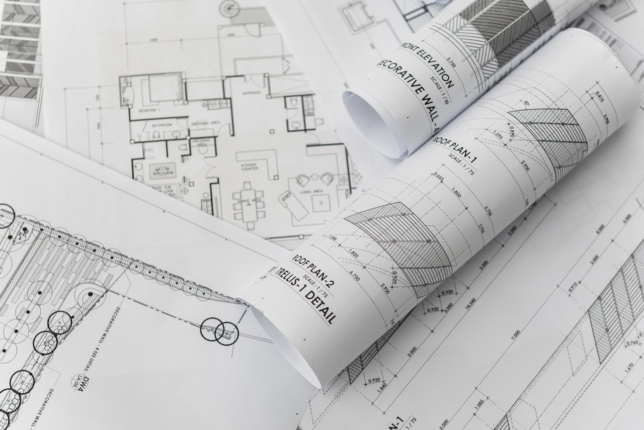
There are several types of construction drawings, each serving a specific purpose. The most common types include:
- Architectural Drawings: These drawings depict the overall design and layout of the building, including floor plans, elevations, sections, and details.
- Structural Drawings: These drawings focus on the structural elements of the building, such as columns, beams, foundations, and load-bearing walls.
- Electrical Drawings: These drawings illustrate the electrical systems within the building, including wiring, outlets, switches, and lighting fixtures.
- Plumbing Drawings: These drawings showcase the plumbing systems, including pipes, fixtures, drains, and water supply lines.
- Mechanical Drawings: These drawings highlight the mechanical systems, such as HVAC (heating, ventilation, and air conditioning) systems, ductwork, and equipment.
Construction drawings are typically created using specialized computer-aided design (CAD) software. This allows for precise measurements, accurate scaling, and easy modifications. The drawings are usually presented in two-dimensional (2D) format, but three-dimensional (3D) renderings and models are also becoming increasingly popular.
Moreover, construction drawings are accompanied by written specifications that provide additional information, such as materials, finishes, and construction techniques. These specifications help contractors and subcontractors understand the requirements and standards for the project.
Construction drawings are not only essential for the building process but also play a crucial role in obtaining permits, securing financing, and ensuring compliance with building codes and regulations. They serve as a communication tool between all stakeholders involved in the construction project and help ensure a successful and efficient build.
Different Types of Construction Drawings
Construction drawings come in various types, each serving a specific purpose in the building process. Understanding these different types will help you navigate through the construction phase with clarity and precision. Here are some of the most common types of construction drawings:
- Architectural Drawings: These drawings provide a visual representation of the building design. They include floor plans, elevations, sections, and details, showing the layout, dimensions, and materials. These drawings are crucial for understanding the overall aesthetics and functionality of the building.
- Structural Drawings: Structural drawings focus on the building’s structural components, such as columns, beams, slabs, and foundations. These drawings provide detailed information on load-bearing capacities, structural connections, and reinforcement details. They ensure the structural integrity and safety of the building.
- Electrical Drawings: Electrical drawings depict the electrical system within the building, including outlets, switches, wiring, and fixtures. They outline the locations of electrical equipment and provide information on the electrical loads and circuitry. These drawings are crucial for proper installation and distribution of power throughout the building.
- Plumbing Drawings: Plumbing drawings depict the layout of the plumbing system, including pipes, fixtures, drains, and water supply lines. These drawings indicate the connections, sizes, and slopes of pipes, as well as the locations of plumbing fixtures. They ensure the proper functioning of water supply and drainage systems.
- Mechanical Drawings: Mechanical drawings showcase the mechanical systems within the building, such as heating, ventilation, and air conditioning (HVAC) systems. These drawings include ductwork, equipment locations, and specifications for HVAC units. They ensure the efficient and comfortable operation of the building’s mechanical systems.
Each of these types of construction drawings serves a specific purpose but are interconnected and depend on each other for a successful construction project. They provide detailed information and instructions for architects, engineers, contractors, and subcontractors to follow during the building process. Collaborating and coordinating these drawings is essential to ensure a coordinated and efficient construction project.
By understanding the different types of construction drawings, you will be able to effectively communicate your design intent, coordinate with the various professionals involved, and ensure the successful completion of your project within budget and schedule.
Tools and Materials Needed
Creating construction drawings requires specific tools and materials to ensure accuracy and precision. Here is a list of the essential tools and materials you will need:
1. Computer-Aided Design (CAD) Software: CAD software is the foundation for creating construction drawings. It allows you to create, edit, and manipulate drawings digitally, providing precise measurements, scaling options, and easy editing capabilities.
2. Computer/Laptop: A computer or laptop with sufficient processing power and memory is essential for running CAD software smoothly. Ensure that your computer meets the recommended system requirements for the CAD software you are using.
3. Design Software: In addition to CAD software, you may need design software specific to the type of drawings you are creating. For example, architectural design software or electrical design software can enhance your ability to create accurate drawings in their respective disciplines.
4. Measuring Tools: Accurate measurements are crucial when creating construction drawings. Have a set of measuring tools such as a tape measure, ruler, or digital calipers to ensure precise dimensions.
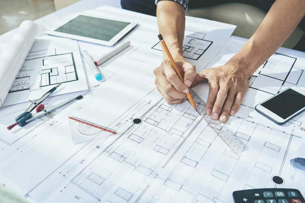
5. Drawing Instruments: Traditional drafting tools can be useful for creating precise drawings by hand. These may include drafting pencils, erasers, rulers, protractors, and compasses.
6. Building Codes and Standards: Familiarize yourself with the relevant building codes and standards for the type of construction project you are working on. This information will guide you in creating drawings that comply with regulations and ensure safety and functionality.
7. Reference Material: Gather reference material related to your specific project, such as architectural plans, design specifications, and technical manuals. These references will provide guidance and ensure accuracy in your drawings.
8. Printing and Plotting Equipment: If you need to print or plot your drawings, ensure you have access to a high-quality printer or plotter that can handle large-format prints. This will allow you to create hard copies of your drawings for review and construction purposes.
9. Collaboration Tools: Communication and collaboration are important when working on construction drawings. Utilize collaboration tools such as project management software, cloud storage platforms, and communication apps to share and exchange drawings with team members and stakeholders.
10. Organizational Supplies: Keep your drawings organized with folders, binders, dividers, and labels. This will help you stay focused and ensure easy access to relevant drawings throughout the project.
By having the right tools and materials, you can create accurate and professional construction drawings that effectively communicate your design intent and provide guidance during the construction process.
Step-by-Step Guide to Creating Construction Drawings
Creating construction drawings can be a complex process, but by following a step-by-step guide, you can ensure efficiency and accuracy. Here is a detailed guide to help you create comprehensive construction drawings:
1. Gather Project Information: Start by gathering all the necessary information about the project, including architectural plans, design specifications, and client requirements. This will serve as the foundation for your construction drawings.
2. Analyze Site Conditions: Visit the project site to assess the existing conditions. Take measurements and note any limitations, such as slopes, obstructions, or utility connections. This information will impact the design and placement of the building components in your drawings.
3. Create a Site Plan: Begin by creating a site plan that shows the layout of the building on the site. Include property boundaries, access points, landscaping elements, and utility connections. Consider the site’s orientation, topography, and drainage when designing the site plan.
4. Design the Floor Plan: Develop the floor plan, which illustrates the layout of each level of the building. Include walls, doors, windows, and major architectural features. Ensure accurate dimensions and consider functionality, circulation, and zoning requirements.
5. Detail Structural Components: Create detailed structural drawings for elements such as columns, beams, and foundations. Include dimensions, reinforcement details, and connection points. Collaborate with structural engineers to ensure the structural integrity and safety of the building.
6. Add Electrical and Plumbing Systems: Incorporate electrical and plumbing systems into your drawings. Show the locations of outlets, switches, fixtures, pipes, drains, and water supply lines. Consider building codes and safety regulations when designing these systems.
7. Incorporate Mechanical Systems: Integrate mechanical systems, such as HVAC ductwork and equipment, into your drawings. Show the layout and specifications of the mechanical components and consider energy efficiency and ventilation requirements.
8. Finalize Construction Drawings: Review and revise your drawings to ensure accuracy, consistency, and compliance with building codes and standards. Coordinate with other professionals involved in the project to address any conflicts or discrepancies.
9. Check for Accuracy and Completeness: Double-check all measurements, dimensions, and annotations in your drawings to ensure accuracy. Verify that all necessary details are included, such as materials, finishes, and fixture specifications.
10. Review and Approve Drawings: Submit your drawings for review and approval by the relevant authorities, clients, and stakeholders. Address any feedback or revisions required and obtain the necessary approvals before proceeding with the construction process.
By following these steps, you can create professional and comprehensive construction drawings that accurately depict your design and provide clear instructions for the construction team. Regular communication and collaboration with other professionals involved in the project are key to ensuring the success of your construction drawings.
Read more: How To Read Construction Drawings
Gathering Project Information
Before embarking on the creation of construction drawings, it is essential to gather all the necessary project information. This stage lays the foundation for the design and ensures that the resulting drawings accurately reflect the client’s needs and requirements. Here are the key steps to effectively gather project information:
1. Client Requirements: Meet with the client to understand their vision and specific requirements for the project. Discuss their goals, functional needs, aesthetic preferences, and any special considerations. This information will guide the design and layout of the building.
2. Architectural Plans: Obtain architectural plans or drawings that provide an overview of the building design. These plans may include floor plans, elevations, and sections. Review them carefully to understand the overall layout and structural elements of the building.
3. Site Documentation: Gather any available site documentation, such as land surveys, topographic maps, and geotechnical reports. These documents provide crucial information about the site’s conditions, including elevations, slopes, and soil composition.
4. Building Codes and Regulations: Familiarize yourself with the building codes and regulations that apply to the project’s location. These codes dictate requirements for structural integrity, fire safety, accessibility, and more. Ensure that your design and drawings comply with these codes.
5. Budget and Schedule: Understand the project’s budget and timeline. This information will influence the design choices and construction methods. It is crucial to align the drawings with the available resources and project milestones.
6. Collaborate with Other Professionals: Coordinate with other professionals involved in the project, such as architects, engineers, and consultants. Engage in discussions to gather their input and ensure that the drawings account for their requirements and recommendations.
7. Research Local Conditions: Consider the local climate, environmental factors, and building materials available in the region. These factors may affect the design decisions and construction methods. Researching local conditions will help you create drawings that are suitable and sustainable for the project location.
8. Document Constraints and Limitations: Identify any constraints or limitations that may impact the design and construction. These constraints could include site restrictions, zoning regulations, easements, or existing structures that need to be preserved.
9. Communication with Stakeholders: Maintain open and ongoing communication with the project stakeholders, including clients, contractors, and regulatory authorities. This ensures that you gather all the relevant information and address any concerns or changes throughout the design process.
10. Record Keeping: Keep a meticulous record of all the project information you gather. This includes meeting notes, emails, sketches, and reference materials. Having organized documentation will help you refer back to important details and prevent any miscommunication or confusion.
By diligently gathering project information, you will have a solid understanding of the client’s requirements, site conditions, regulations, and project constraints. This information will serve as a valuable foundation for creating accurate and comprehensive construction drawings that align with the project goals and deliver successful outcomes.
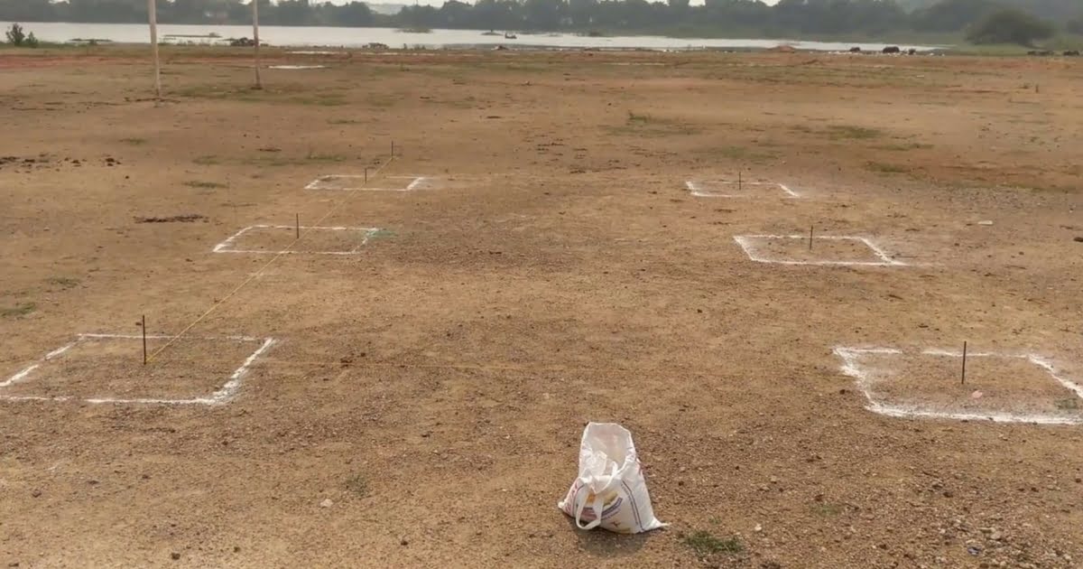
Analyzing Site Conditions
Analyzing site conditions is a crucial step in creating construction drawings as it allows you to understand the existing landscape and infrastructure that will influence the design and construction process. Here are the key factors to consider when analyzing site conditions:
1. Site Visit: Start by visiting the project site to gain firsthand knowledge of the site’s characteristics. Observe the terrain, vegetation, neighboring structures, and any existing features that may impact the design and construction.
2. Site Measurements: Take accurate measurements of the site, including distances between property boundaries, topographical features, and existing structures. Use measuring tools such as a tape measure or laser distance meter to ensure precision.
3. Topography: Evaluate the site’s topography, including slopes, changes in elevation, and natural features like rivers or hills. This information will help determine the most suitable building placement and foundation design.
4. Soil Composition: Conduct a soil analysis to understand the soil composition and its bearing capacity. This information is crucial for determining foundation design, excavation requirements, and overall stability of the structure.
5. Drainage and Water Management: Assess the site’s drainage patterns and existing water sources, such as creeks or underground water tables. Consider how surface water will be managed, and ensure that the design addresses any potential water-related issues.
6. Environmental Factors: Identify any environmental factors that may impact the project, such as nearby wetlands, protected areas, or endangered species habitats. Adhere to environmental regulations and design considerations to minimize ecological impact.
7. Utilities and Services: Locate and document the location of existing utility lines, such as water, gas, electricity, and sewage. Take note of any service connections or easements that may affect the building’s design and placement.
8. Accessibility and Transportation: Assess the site’s accessibility, including roadways, parking, and pedestrian access. Consider the ease of transportation and potential traffic impacts during construction and operation of the building.
9. Safety and Security: Recognize any potential safety hazards or security concerns on the site. This includes identifying nearby high-risk areas or potential risks associated with the construction process. Mitigate these risks in the design and construction phases.
10. Personal Protective Equipment (PPE): When conducting site visits, prioritize safety by wearing appropriate personal protective equipment (PPE) such as hard hats, safety vests, and steel-toed boots. Follow safety protocols and guidelines during your assessment.
By thoroughly analyzing the site conditions, you will gain valuable insights that will inform the design process and ensure that your construction drawings align with the site’s unique characteristics. It allows you to create drawings that integrate harmoniously with the environment while addressing practical considerations and complying with regulations.
Creating a Site Plan
A site plan is a critical component of construction drawings as it provides an overview of the entire project site and serves as the foundation for the building design. It communicates the placement, orientation, and relationship of various elements on the site. Here are the key steps to create a comprehensive site plan:
1. Gather Existing Site Information: Collect all available documentation, including survey reports, topographic maps, and any site-specific data. This information will aid in accurately representing the site’s features and constraints.
2. Determine the Scale: Select an appropriate scale for your site plan. The scale should consider the size of the project and the level of detail you wish to convey. A standard scale, such as 1:100 or 1:200, is often used for clarity.
3. Establish the Site Boundary: Clearly define the boundaries of the site, including property lines and adjacent land uses. Consult legal surveys or property documents to ensure accuracy.
4. Include Existing Structures and Features: Map out any existing buildings, structures, or features within and adjacent to the site. This includes trees, driveways, parking areas, and utilities. Accurately depict their location and dimensions.
5. Highlight Access Points: Indicate the main access points to the site, such as roads, driveways, or walkways. Consider circulation patterns for vehicles and pedestrians to ensure efficient access and safety.
6. Show Grading and Topography: Represent the existing topography, including contours, elevation lines, and significant changes in grade. This information is crucial for site planning and evaluating the impact of grading on drainage and construction requirements.
7. Depict Landscaping Elements: Illustrate landscape elements, such as vegetation, gardens, and hardscape features, like benches or pathways. These elements contribute to the overall aesthetic and functionality of the site.
8. Consider Environmental Factors: Incorporate environmental considerations into the site plan. Account for natural features like wetlands, wildlife habitats, or watercourses, and ensure compliance with relevant environmental regulations.
9. Indicate Utility Connections: Display the locations of utility connections, such as water, gas, electricity, and sewage lines. This ensures that adequate utility access and connections are planned for the building design.
10. Add Site Notations and Legends: Include a notation key and legends to explain the symbols, abbreviations, and colors used in the site plan. This enhances clarity and ensures accuracy when interpreting the plan.
Creating a comprehensive site plan requires attention to detail and accurate representation of existing site conditions. The site plan will serve as an essential reference throughout the design and construction process, providing a clear overview of the project site and guiding subsequent steps in the creation of construction drawings.
When creating construction drawings, be sure to include all necessary dimensions, notes, and details to clearly communicate the design intent to contractors and builders. Accuracy and clarity are key.
Designing the Floor Plan
The floor plan is a key component of construction drawings as it outlines the layout and organization of each floor level in a building. It serves as a visual representation of the building’s interior spaces and is crucial for understanding the flow, functionality, and dimensions of the structure. Here are the steps to design an effective floor plan:
1. Gather Requirements: Start by understanding the functional requirements of the space. Consider the intended use, occupancy, and specific needs of each room or area within the building.
2. Determine Room Locations: Establish the locations of rooms and spaces within the building. Consider factors such as adjacency, privacy, and access to natural light and views.
3. Define Room Sizes: Determine the dimensions of each room, taking into account the activities that will take place within them. Ensure that there is adequate space for furniture, equipment, and circulation.
4. Consider Circulation: Plan for efficient circulation throughout the building. Design hallways, corridors, and stairwells in a manner that minimizes dead-end spaces and allows for easy movement between rooms.
5. Incorporate Building Codes and Regulations: Ensure compliance with building codes and regulations. Consider requirements for minimum room dimensions, ceiling heights, and accessibility standards, including wheelchair accessibility and egress routes.
6. Design Structural Elements: Integrate structural elements, such as walls, columns, and beams, into the floor plan. Ensure that they align with the overall design and do not obstruct the flow or functionality of the space.
7. Define Windows and Doors: Determine the locations of windows and doors to optimize natural light, ventilation, and views. Consider the orientation of the building and the relationship between interior and exterior spaces.
8. Address Functionality: Design spaces with functionality in mind. Consider efficient placement of plumbing fixtures, electrical outlets, and HVAC vents to ensure convenience and optimal use of resources.
9. Create Clear Labels and Annotations: Label each room and space on the floor plan to create a clear understanding of its purpose. Include room numbers, names, or specific designations to assist with communication and future reference.
10. Review and Revise: Regularly review and revise the floor plan design to ensure accuracy, functionality, and alignment with the project goals. Seek input from stakeholders, architects, and engineers to enhance the quality of the design.
By following these steps, you can create a well-designed floor plan that meets the requirements of the space and facilitates efficient use of the building. The floor plan provides a clear understanding of the interior layout, aiding in the subsequent steps of creating detailed construction drawings.
Read more: What Size Are Construction Drawings
Detailing Structural Components
Detailing the structural components in construction drawings is a critical step to ensure the structural integrity and safety of the building. These drawings provide precise information about the design, dimensions, and construction techniques related to the structural elements. Here are the key steps to effectively detail structural components:
1. Collaborate with Structural Engineers: Work closely with structural engineers to understand the specific requirements and design considerations for the project. Collaborative discussions will help ensure that the structural components align with the overall design and meet engineering standards.
2. Determine Load-Bearing Elements: Identify and designate load-bearing elements, such as columns, beams, walls, and foundations. These components are responsible for supporting the weight of the building and transferring loads to the ground.
3. Specify Materials: Specify the type of materials to be used for each structural component, such as reinforced concrete, steel, or timber. Consider factors such as cost, availability, durability, and strength requirements when selecting materials.
4. Establish Dimensions: Determine the dimensions of each structural component, including length, width, and height. Ensure that the dimensions meet the structural and architectural requirements while considering space constraints and aesthetic considerations.
5. Provide Clear Detail Drawings: Create detailed drawings for each structural component, illustrating the connections, joint details, reinforcements, and anchorage methods. Include dimensions, sections, and elevations to accurately convey the construction details
6. Include Structural Notes: Add structural notes to the drawings to indicate specific requirements or guidelines for the construction of the structural components. These notes may include information about fireproofing, waterproofing, or special construction techniques.
7. Consider Structural Codes and Regulations: Ensure compliance with structural codes and regulations governing the construction of the building. Address factors such as wind loads, seismic considerations, and other environmental forces in the design and detailing of the structural components.
8. Coordinate with Other Disciplines: Collaborate with other disciplines, such as architectural and mechanical, to ensure proper coordination and integration of structural components with other building systems. This coordination avoids conflicts and ensures safe and efficient construction.
9. Periodic Quality Control Checks: Perform periodic quality control checks to validate the accuracy and precision of the structural component detailing. This helps to identify any discrepancies or errors that could affect the structural stability of the building.
10. Review and Approval: Engage in thorough reviews and obtain approvals from relevant authorities, such as structural engineers, architects, and building officials, to ensure that the structural components are in accordance with the design intent and meet the required standards.
By meticulously detailing the structural components in the construction drawings, you ensure the structural integrity and safety of the building. These drawings serve as a crucial reference for contractors and construction teams during the actual construction phase and play a vital role in bringing the design to life.
Adding Electrical and Plumbing Systems
The integration of electrical and plumbing systems into construction drawings is crucial for the functionality and efficiency of a building. Properly documenting these systems ensures that electrical and plumbing components are accurately placed and connected. Here are the steps to effectively add electrical and plumbing systems to the construction drawings:
1. Plan Layouts: Determine the layout and placement of electrical and plumbing components. Consider factors such as functionality, code requirements, accessibility, and coordination with architectural and structural elements.
2. Electrical System: Design the electrical system by creating a comprehensive electrical plan. Include outlets, switches, lighting fixtures, and other electrical devices. Indicate the location of main electrical panels, subpanels, and distribution points.
3. Plumbing System: Incorporate the plumbing system into the drawings. Show the placement of pipes, drains, fixtures, and water supply lines. Indicate connections to the main water supply, sewage, and drainage systems.
4. Electrical Outlets and Switches: Clearly mark the location of electrical outlets, switches, and other devices on the construction drawings. Provide specific information, such as the number of outlets, voltage requirements, and switch types.
5. Lighting Fixtures: Use symbols and notations to represent lighting fixtures and their corresponding locations. Indicate the type of fixture, wattage, and any special considerations, such as emergency lighting or dimming controls.
6. Plumbing Fixtures: Depict plumbing fixtures such as sinks, toilets, showers, and water fountains on the drawings. Include information about the type, size, and specifications of each fixture.
7. Pipe and Wiring Routing: Show the routing of electrical wiring and plumbing pipes within the building. Use clear symbols and labels to indicate the size, material, and routing of pipes and wiring to facilitate installation.
8. Safety Considerations: Ensure compliance with electrical and plumbing codes and regulations. Incorporate safety features such as grounding, GFCI (Ground Fault Circuit Interrupter) outlets, and backflow prevention devices for plumbing systems.
9. Coordination with Other Disciplines: Collaborate with architects, structural engineers, and mechanical engineers to coordinate the electrical and plumbing systems with other building components. This ensures proper integration and eliminates conflicts.
10. Review and Approval: Conduct thorough reviews of the electrical and plumbing drawings and obtain approvals from relevant authorities. This ensures that the design complies with regulations and meets the needs of the building occupants.
Adding electrical and plumbing systems to construction drawings facilitates the installation and ensures the functionality and safety of a building. Accurate and detailed documentation allows contractors and subcontractors to execute the design effectively, leading to a successful construction project.
Incorporating Mechanical Systems
Incorporating mechanical systems into construction drawings is vital to ensure the proper functioning and comfort of a building. Mechanical systems include heating, ventilation, and air conditioning (HVAC) systems, as well as other equipment that supports the building’s mechanical operations. Here are the steps to effectively incorporate mechanical systems into construction drawings:
1. Collaborate with Mechanical Engineers: Work closely with mechanical engineers to understand the specific requirements and design considerations of the mechanical systems. Collaboration ensures that the design of the mechanical systems aligns with the overall building design.
2. Determine HVAC Zones: Divide the building into appropriate HVAC zones based on factors such as occupancy, use, and thermal loads. Different areas may require different heating or cooling requirements depending on the intended use of the space.
3. Design HVAC Layout: Create an HVAC plan that depicts the layout of heating, cooling, and air distribution systems. Indicate the placement of air handlers, ventilation units, ductwork, and diffusers in coordination with other building components.
4. System Sizing and Equipment: Size the HVAC equipment based on heating and cooling loads calculated by mechanical engineers. Include specifications of the equipment, such as capacity, efficiency ratings, and control systems.
5. Air Distribution: Show the routing of ductwork and vents throughout the building. Indicate the size, material, and fittings for the ducts, along with the location and types of diffusers or grilles.
6. Ventilation and Exhaust Systems: Incorporate ventilation and exhaust systems into the mechanical drawings. Show the location and specifications for air handling units, exhaust fans, and ventilation ducts to ensure adequate air quality and circulation.
7. Plumbing Systems: Coordinate plumbing systems related to mechanical operations, such as hot water supply, drainage, and waste disposal. Include the routing of pipes, location of water heaters, and any required plumbing fixtures or equipment.
8. Fire Suppression and Safety: Account for fire suppression systems, such as sprinklers or fire suppression equipment, in the mechanical drawings. Ensure compliance with fire safety codes and regulations.
9. Energy Efficiency Considerations: Design mechanical systems with energy efficiency in mind. Incorporate features such as variable speed drives, energy recovery systems, and zoning controls to optimize energy usage.
10. Review and Approval: Conduct thorough reviews of the mechanical drawings to ensure accuracy and compliance with codes and regulations. Obtain approvals from relevant authorities to ensure that the mechanical systems meet the necessary standards.
Incorporating mechanical systems into construction drawings is essential for the comfort, functionality, and energy efficiency of a building. Detailed drawings help allocate space, facilitate installation, and ensure the smooth operation of these systems, contributing to a successful construction project.
Finalizing Construction Drawings
The finalizing stage of construction drawings is a critical step to ensure the accuracy, completeness, and quality of the drawings before they are issued for construction. Here are the key steps to finalize construction drawings:
1. Review for Accuracy: Conduct a thorough review of the drawings to verify that all dimensions, measurements, and annotations are accurate. Check for any inconsistencies or errors that may affect the construction process.
2. Coordinate with Other Disciplines: Collaborate with architects, engineers, and other professionals involved in the project to ensure that the drawings are coordinated and aligned with other disciplines, such as architecture, structure, electrical, plumbing, and mechanical.
3. Check for Compliance: Ensure that the construction drawings comply with applicable building codes, regulations, and standards. Address any issues or deviations that may affect legal requirements or building permit processes.
4. Clarify Design Intent: Review the drawings to ensure that the design intent has been accurately captured. Confirm that the visual representations of the building accurately reflect the original design concept and meet the client’s requirements.
5. Verify Markups and Revisions: Address any markups or revisions that were made during the review process. Verify that all requested changes and revisions have been properly incorporated into the final drawings.
6. Ensure Clarity and Readability: Confirm that the drawings are clear, legible, and easy to understand. Use appropriate labels, symbols, scales, and legends to enhance the clarity and readability of the drawings for the construction team.
7. Check Annotation and Notations: Review the annotations and notations on the drawings to ensure that they are accurate, consistent, and serve their intended purpose. Verify that all necessary information, such as materials, finishes, and construction techniques, is properly indicated.
8. Formatting and Presentation: Pay attention to the overall formatting and presentation of the drawings. Ensure that they are well-organized, properly formatted, and meet any specific requirements or standards set by the client, regulatory agencies, or project guidelines.
9. Finalize Drawing Sets: Compile the complete set of finalized construction drawings, including all necessary sheets, plans, elevations, sections, details, schedules, and any required specifications. Organize the drawings in a logical and structured manner.
10. Issue for Construction: Once the drawings have been thoroughly reviewed, revised, and finalized, issue them for construction. Distribute the drawings to the construction team, contractors, and other stakeholders involved in the project to commence the construction phase.
By following these steps, you can ensure that the construction drawings are accurate, comprehensive, and ready to guide the construction process. Finalizing the drawings with attention to detail and quality is essential for a successful and efficient construction project.
Read more: What Is A Shop Drawing In Construction
Checking for Accuracy and Completeness
Checking construction drawings for accuracy and completeness is a crucial step to ensure that the drawings are error-free, consistent, and ready for implementation. Conducting a thorough review helps identify any discrepancies, omissions, or mistakes that may affect the construction process and helps maintain project quality. Here are the key steps for checking construction drawings:
1. Verify Dimensions: Check all dimensions, measurements, and scale ratios in the drawings to ensure accuracy. Confirm that they align with the design intent, architectural plans, and relevant building codes and standards.
2. Review Annotations: Check all annotations, notes, and labels on the drawings. Confirm that they provide clear and concise information about materials, finishes, equipment, and construction techniques.
3. Coordinate with Other Disciplines: Collaborate with other disciplines, such as architectural, structural, electrical, plumbing, and mechanical, to ensure coordination and integration. Verify that the drawings align with the requirements and specifications of all disciplines.
4. Check for Consistency: Ensure consistency across different sheets and sections of the drawings. Verify that annotations, symbols, and graphical representations are uniform throughout the drawings.
5. Confirm Compliance: Review the drawings for compliance with local building codes, regulations, and standards. Make sure that all design elements, structural components, electrical and plumbing systems, and safety measures meet the required specifications.
6. Evaluate Sequencing and Flow: Assess the logical sequencing and flow of information in the drawings. Verify that the drawings progress in a logical order, allowing for an efficient understanding of the construction process.
7. Address Conformance Issues: Identify any conformance issues that deviate from the original design, project requirements, or contractual obligations. Address these issues promptly and work with the necessary parties to resolve them.
8. Validate Calculations and Formulas: Check calculations and formulas related to structural elements, load-bearing capacity, electrical loads, plumbing flow rates, and other technical calculations. Ensure the accuracy of these calculations to maintain the overall integrity of the project.
9. Create a Checklist: Develop a checklist or review document that outlines the specific criteria and requirements to check for accuracy and completeness. This checklist will serve as a reference guide and ensure that no aspect of the drawing review process is overlooked.
10. Seek Independent Reviews: Consider engaging third-party experts or consultants to conduct independent reviews of the drawings. Their fresh perspective can help identify any potential issues or oversights that may have been missed.
Thoroughly checking construction drawings for accuracy and completeness is essential to ensure that the design is accurately communicated and can be implemented with minimum errors. This diligent review process mitigates risks, reduces rework, and helps deliver a successful construction project.
Reviewing and Approving Drawings
The review and approval phase of construction drawings is a critical step to ensure that the drawings align with the project requirements, design intent, and regulatory standards. This process involves careful scrutiny by stakeholders and professionals involved in the project. Here are the key steps for reviewing and approving construction drawings:
1. Establish a Review Team: Assemble a review team consisting of architects, engineers, contractors, and other relevant stakeholders. Each member should have expertise in their respective disciplines and a thorough understanding of the project requirements.
2. Conduct a Comprehensive Review: Thoroughly examine all aspects of the construction drawings, including architectural, structural, electrical, plumbing, and mechanical components. Assess the drawings for accuracy, consistency, compliance with codes, and coordination among disciplines.
3. Verify Design Intent: Ensure that the drawings accurately represent the design intent and meet the client’s requirements. Review the drawings in conjunction with the project specifications to confirm that all design parameters have been incorporated effectively.
4. Check for Technical Accuracy: Scrutinize the drawings for technical accuracy, including dimensions, symbols, labels, and notations. Verify that all calculations, formulas, and material specifications are correct and align with industry standards.
5. Assess Compliance: Confirm that the drawings comply with applicable building codes, regulations, and standards. Verify that the design meets safety, accessibility, and environmental requirements, addressing any potential conflicts or non-compliance issues.
6. Seek Constructability: Ensure that the drawings are constructible and practical. Assess the feasibility of the design in terms of material availability, construction techniques, and the local construction industry’s capabilities.
7. Request and Address Revisions: If any issues or discrepancies are identified during the review process, request revisions from the design team. Collaborate with the team to address and resolve any concerns or changes necessary to improve the accuracy and quality of the drawings.
8. Finalize and Document Approvals: Once all revisions have been made and the drawings are deemed satisfactory, document the approvals from the review team and relevant stakeholders. Maintain a record of the approved drawings for reference and future documentation.
9. Obtain Permits and Clearances: Utilize the approved construction drawings to apply for necessary permits and clearances from local authorities. Ensure compliance with their specific requirements and seek their final approval before commencing construction.
10. Communicate and Distribute: Share the final approved drawings with all stakeholders, including the construction team, contractors, subcontractors, and suppliers. Promote effective communication to ensure a clear understanding and successful implementation of the project.
The review and approval process is crucial to ensure the quality, accuracy, and compliance of construction drawings. It provides a platform for collaboration, enhances the project’s success, and sets the stage for a smooth and efficient construction phase.
Conclusion
Creating comprehensive and accurate construction drawings is an essential step in the building process. These drawings serve as a roadmap for architects, engineers, contractors, and other professionals involved in the construction project. They provide the necessary guidance and instructions for bringing a design to life while ensuring compliance with building codes, safety regulations, and industry standards.
Throughout this article, we have explored the various aspects of creating construction drawings, from understanding their importance to the step-by-step process of designing and finalizing them.
We began by emphasizing the significance of understanding construction drawings and their different types, highlighting their role in communicating design intent and guiding the construction process.
Then, we delved into the tools and materials needed, emphasizing the importance of utilizing specialized software, gathering necessary resources, and ensuring effective collaboration with stakeholders.
We provided a step-by-step guide to creating construction drawings, starting from gathering project information, analyzing site conditions, creating site plans, designing floor plans, detailing structural components, and incorporating electrical, plumbing, and mechanical systems.
We also highlighted the importance of reviewing and finalizing construction drawings, emphasizing the need for accuracy, completeness, and compliance with regulations.
Ultimately, the review and approval process was emphasized as a critical step in ensuring the quality, accuracy, and adherence of the construction drawings to project requirements and regulatory standards.
In conclusion, construction drawings are the backbone of any building project. They enable the visualization and coordination of design elements, structural components, and systems. With attention to detail, collaboration, and adherence to standards, accurate construction drawings ensure the successful execution of a construction project and contribute to safe, functional, and visually appealing built environments.
Frequently Asked Questions about How To Do Construction Drawings
Was this page helpful?
At Storables.com, we guarantee accurate and reliable information. Our content, validated by Expert Board Contributors, is crafted following stringent Editorial Policies. We're committed to providing you with well-researched, expert-backed insights for all your informational needs.


0 thoughts on “How To Do Construction Drawings”