Home>diy>Building & Construction>What Size Are Construction Drawings

Building & Construction
What Size Are Construction Drawings
Modified: January 4, 2024
Learn about the size of construction drawings in building construction. Gain insights on the standard dimensions and importance.
(Many of the links in this article redirect to a specific reviewed product. Your purchase of these products through affiliate links helps to generate commission for Storables.com, at no extra cost. Learn more)
Introduction
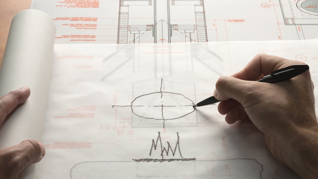
Welcome to the world of construction, where complex ideas come to life through meticulous planning and execution. One of the most crucial aspects of any construction project is the creation and utilization of construction drawings. These drawings serve as the blueprint for the entire project, guiding architects, engineers, and contractors in every step of the construction process.
In this article, we will delve into the topic of construction drawings and specifically focus on their size. Have you ever wondered why construction drawings vary in size? What factors influence their dimensions? Why is it important to standardize construction drawing sizes? We will explore these questions and more, as we unravel the mysteries behind the size of construction drawings.
Let’s dive in and discover the fascinating world of construction drawings and explore the reasons behind their diverse sizes.
Key Takeaways:
- Standardizing construction drawing sizes is crucial for efficient collaboration, accurate scaling, and adherence to regulations. It fosters industry-wide consistency, streamlines processes, and enhances the overall quality of construction projects.
- Understanding the size of construction drawings is essential for effective communication and coordination. Standardized sizes promote easy interpretation, convenient reproduction, and organized storage, contributing to the success of construction projects.
Read more: What Is A Shop Drawing In Construction
Role of Construction Drawings in the Construction Process
Construction drawings play a pivotal role in the construction process. They serve as a visual representation of the proposed project, illustrating the design, dimensions, and specifications required for its successful completion. These drawings act as a communication tool, enabling clear and precise understanding among all stakeholders involved.
One of the primary functions of construction drawings is to guide architects and engineers in creating the initial design concept. These drawings outline the structural components, spatial arrangements, and overall aesthetics of the project. They provide a visual representation of the intended construction, allowing the design team to refine and improve the concept before moving forward.
Once the design is finalized, construction drawings serve as a reference point for the contractors and subcontractors involved in the project. These drawings provide detailed instructions on how to execute the construction, including the placement of walls, installation of electrical and plumbing systems, and the positioning of structural elements.
Furthermore, construction drawings act as a basis for acquiring permits and approvals from regulatory authorities. Building codes and regulations require submission of precise and accurate drawings, demonstrating compliance with safety standards and zoning requirements.
During the construction phase, these drawings act as a guide for project managers and site supervisors. They help in coordinating various trades and ensure that the work is being done according to the approved design. Construction drawings also aid in quantity takeoffs, allowing contractors to estimate the materials and resources required for the project accurately.
Another crucial aspect of construction drawings is their role in communication and coordination between different teams and professionals. These drawings facilitate effective collaboration among architects, engineers, contractors, subcontractors, and suppliers, ensuring that everyone is on the same page and working towards a common goal.
In summary, construction drawings serve as a visual roadmap for the construction project. They act as a communication tool, facilitate coordination, ensure adherence to regulations, guide construction activities, and contribute to the successful completion of the project.
Understanding the Size of Construction Drawings
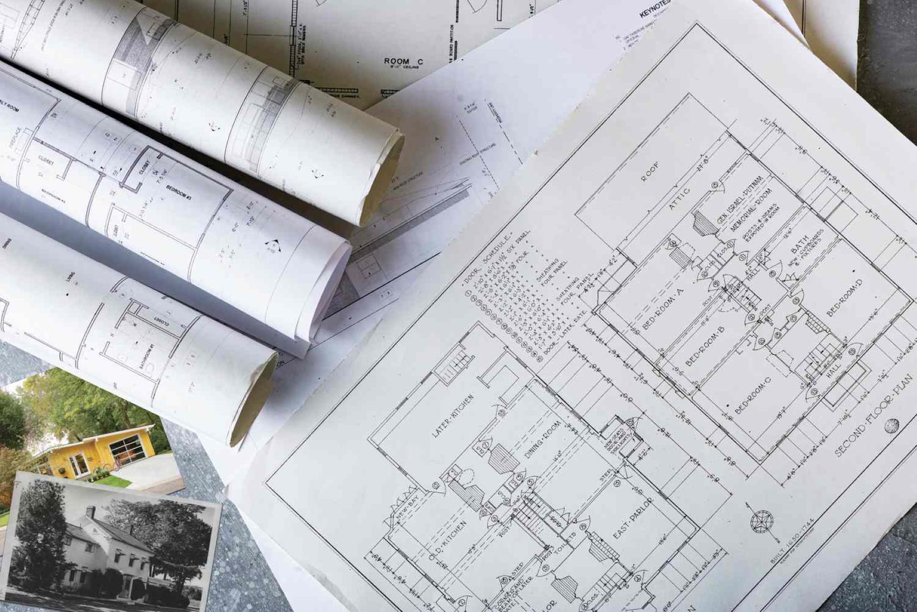
Construction drawings can come in various sizes, ranging from small-scale sketches to large-scale blueprints. Understanding the size of construction drawings is crucial for both the professionals involved in the project and anyone reviewing or using the drawings.
The size of a construction drawing refers to its physical dimensions, typically measured in width and height. Commonly used measurement units for construction drawings include inches, feet, millimeters, and centimeters.
The choice of size for construction drawings depends on several factors, including the complexity of the project, level of detail required, and the type of information that needs to be conveyed.
Smaller-sized drawings, such as 8.5″x11″ or A4, are commonly used for general plans and sketches. These drawings are often used during the initial design phase or for simple projects. They are convenient to carry, easy to review, and can be easily reproduced.
For more detailed and complex projects, larger-sized drawings are often preferred. These can range from 18″x24″ to 36″x48″ or larger. The larger size allows for more intricate detailing, including precise measurements, annotations, and notations for various construction elements.
In addition to the physical dimensions, the scale of construction drawings is also important in understanding their size. The scale represents the proportion between the drawing and the actual physical dimensions of the project. For example, a 1:50 scale means that every unit on the drawing represents 50 units in real life.
Large-scale construction drawings, such as floor plans, elevations, and sections, provide a detailed representation of the project. These drawings are typically used by architects, engineers, and contractors to understand the specific dimensions, angles, and relationships between various elements of the construction.
Understanding the size of construction drawings is essential for accurately interpreting and utilizing the information provided. It allows professionals to effectively communicate and coordinate during the construction process and ensures that the project is executed as per the intended design.
Factors Influencing the Size of Construction Drawings
The size of construction drawings can be influenced by several factors that are specific to each construction project. Understanding these factors can help professionals determine the most appropriate size for their drawings. Let’s explore some key factors that influence the size of construction drawings:
1. Level of Detail: The level of detail required in the construction drawings plays a significant role in determining their size. Projects that require intricate detailing, such as complex structural elements or sophisticated mechanical systems, may necessitate larger drawings to accommodate the additional information.
2. Scope of the Project: The size of construction drawings can also be influenced by the scope of the project. Large-scale projects, such as high-rise buildings or expansive industrial complexes, may require larger drawings to encompass the extensive layout and intricate design elements.
3. Accessibility and Portability: The accessibility and portability of construction drawings are important considerations. Smaller-sized drawings are more convenient to handle, store, and transport, making them suitable for on-site use or when frequent referencing is required.
4. Required Scale: The scale at which the drawings need to be printed or displayed can also impact their size. Larger scales, such as 1:50 or 1:100, may require larger drawings to accurately represent the details and dimensions of the project.
5. Printing and Reproduction Technology: The printing and reproduction technology available also play a role in determining the size of construction drawings. Advancements in printing technology have made it easier to reproduce larger-sized drawings without sacrificing quality, allowing for more detailed and comprehensive representations.
6. Regulatory Requirements: Local building codes and regulations may have specific requirements regarding the size of construction drawings. Compliance with these regulations is crucial, and professionals must ensure that their drawings meet the specified size guidelines.
7. Collaboration and Communication: The size of construction drawings can impact collaboration and communication among project stakeholders. Larger drawings may provide more clarity and ease of review during design reviews, coordination meetings, and stakeholder presentations.
It is important for professionals to evaluate these factors and make informed decisions regarding the size of their construction drawings. By considering these factors, architects, engineers, and contractors can produce drawings that effectively communicate the design intent, facilitate construction coordination, and ensure project success.
Construction drawings are typically printed on large sheets, such as 24″x36″ or 30″x42″. They may also be available in smaller sizes for easier handling on site.
Common Sizes of Construction Drawings
Construction drawings are available in various sizes, each serving a specific purpose and catering to different project requirements. While the size of construction drawings can vary based on specific project needs, there are some common sizes that are widely used in the industry. Let’s take a look at these common sizes:
1. ISO A-Series: The ISO A-series is a standardized set of sizes commonly used in construction drawings. The A0 size is the largest, measuring 841mm x 1189mm (33.1″ x 46.8″), and it is typically used for large-scale architectural plans, site plans, and floor plans. The subsequent sizes, such as A1, A2, A3, and A4, are progressively smaller and used for more detailed drawings.
2. Architectural (ARCH) Series: The architectural series, also known as the ARCH series, is another popular set of sizes for construction drawings. The ARCH D size, measuring 24″ x 36″, is commonly used for architectural plans, elevations, and sections. The ARCH E1 size, which is 30″ x 42″, is often used for larger-scale drawings that require more detail.
3. Engineering (ENG) Series: The engineering series, also known as the ENG series, is commonly used for technical drawings and construction documentation. The ENG D size, measuring 22″ x 34″, is commonly used for engineering plans, structural drawings, and mechanical system layouts. The ENG E size, which is 34″ x 44″, is often used for larger-scale engineering drawings.
4. ANSI Series: The ANSI series, established by the American National Standards Institute, is widely used in the United States for construction drawings. The ANSI D size, measuring 22″ x 34″, is commonly used for architectural and engineering drawings. The ANSI E size, measuring 34″ x 44″, is often used for larger-scale drawings that require more detail.
5. Letter and Legal Sizes: In addition to the above standardized sizes, letter-size (8.5″ x 11″) and legal-size (8.5″ x 14″) drawings are commonly used for smaller-scale construction plans, sketches, and general documentation. These sizes are convenient for portability and ease of reproduction, making them suitable for smaller projects or on-site reference.
It is important to note that these are just a few of the common sizes used in construction drawings. Depending on project requirements, specialized drawings may also be created in custom sizes to suit specific needs. The choice of size ultimately depends on factors such as project scale, level of detail, and regional standards.
By understanding the common sizes of construction drawings, professionals can effectively communicate and collaborate with stakeholders, ensuring clear and accurate representation of the project.
Read more: What Is IFC Drawings In Construction
Importance of Standardizing Construction Drawing Sizes
Standardizing construction drawing sizes is of paramount importance in the construction industry. It ensures consistency, clarity, and effective communication among project stakeholders, facilitating a smoother construction process. Let’s explore the key reasons why standardizing construction drawing sizes is crucial:
1. Easy Interpretation: Standardized drawing sizes allow for easier interpretation and understanding of construction plans. When all professionals involved are familiar with and accustomed to specific sizes, it becomes effortless to navigate through the drawings, locate information, and comprehend the design intent.
2. Efficient Collaboration: Standardized drawing sizes promote efficient collaboration among architects, engineers, contractors, and subcontractors. When everyone is working with the same set of standard sizes, there is a seamless exchange of information, improved coordination, and minimized confusion. This streamlines decision-making processes and ensures that all parties are on the same page.
3. Accurate Scaling: Standardized sizes enable accurate scaling of drawings. Engineers and contractors rely on the dimensions provided in the drawings to carry out construction activities precisely. When drawings adhere to standardized sizes, it becomes easier to interpret scale ratios and distances, resulting in accurate execution of the project.
4. Convenient Reproduction: Standardized drawing sizes facilitate easy reproduction of drawings using standard printing equipment. Architects, engineers, and contractors often need multiple copies of the drawings for various purposes, such as subcontracting bids, on-site reference, or documentation. Standardized sizes make the reproduction process more efficient, reducing time and effort.
5. Adherence to Regulations: Many building codes and regulations require construction drawings to meet specific size guidelines. Adhering to these standards ensures compliance with regulatory requirements and facilitates the approval process. Standardized drawing sizes simplify the review and approval procedures, allowing for smoother interactions with regulatory authorities.
6. Storage and Archiving: Standardized drawing sizes make storage and archiving more organized and manageable. When all drawings are of uniform size, it is easier to store them in filing cabinets or digitally archive them in a structured manner. This facilitates quick retrieval and reference whenever needed.
7. Industry-wide Consistency: Standardizing drawing sizes promotes consistency across the construction industry. It enables professionals to collaborate seamlessly, regardless of geographic location or project type. This consistency ensures greater efficiency, transparency, and accuracy in the design and construction processes.
By standardizing construction drawing sizes, professionals can enhance communication, accuracy, and efficiency throughout the construction project. It fosters a cohesive working environment, minimizes errors and misunderstandings, and contributes to the successful completion of projects. Embracing standardization is a necessary step towards streamlining processes, improving productivity, and elevating the overall quality of construction projects.
Conclusion
Construction drawings hold immense significance in the construction industry, serving as the guiding blueprint for successful project execution. Understanding the size of construction drawings is crucial for effective communication, collaboration, and accurate representation of the intended design. By standardizing construction drawing sizes, professionals can enhance clarity, consistency, and efficiency throughout the construction process.
From ISO A-Series to ARCH and ENG series, there are numerous common sizes used in construction drawings. Each size serves a specific purpose, catering to project requirements, level of detail, and ease of use. Standardizing these sizes promotes easy interpretation, efficient collaboration, accurate scaling, convenient reproduction, adherence to regulations, and streamlined storage and archiving processes.
Standardizing construction drawing sizes facilitates a cohesive working environment, ensuring that all project stakeholders are on the same page. It minimizes errors, enhances clarity, and improves coordination among architects, engineers, contractors, and subcontractors. Additionally, adhering to standardized sizes enables compliance with building codes and regulations, streamlines the approval process, and contributes to industry-wide consistency.
It is important for professionals in the construction industry to embrace standardization and utilize common sizes for construction drawings. This practice not only improves communication and collaboration but also enhances the overall efficiency and success of construction projects. By working with standardized sizes, professionals can achieve greater accuracy, productivity, and client satisfaction.
In conclusion, understanding and standardizing the size of construction drawings are essential for seamless project execution. Through standardized sizes, professionals can effectively convey design intent, improve coordination, and ensure precision in the construction process. It is clear that standardizing construction drawing sizes is not only practical but also vital for the success of construction projects and the industry as a whole.
Frequently Asked Questions about What Size Are Construction Drawings
Was this page helpful?
At Storables.com, we guarantee accurate and reliable information. Our content, validated by Expert Board Contributors, is crafted following stringent Editorial Policies. We're committed to providing you with well-researched, expert-backed insights for all your informational needs.


0 thoughts on “What Size Are Construction Drawings”