Home>diy>Architecture & Design>What Are CAD Drawings

Architecture & Design
What Are CAD Drawings
Modified: October 28, 2024
Learn about CAD drawings and their importance in architecture design. Discover how these digital representations help visualize and communicate building plans.
(Many of the links in this article redirect to a specific reviewed product. Your purchase of these products through affiliate links helps to generate commission for Storables.com, at no extra cost. Learn more)
Introduction
Welcome to the world of CAD drawings, where imagination meets precision, creativity combines with technology, and designs come to life. CAD, which stands for Computer-Aided Design, has revolutionized the field of architecture and engineering, providing designers with powerful tools to create and visualize their ideas in a digital format.
In this article, we will explore the fascinating world of CAD drawings, diving into their definition, importance, types, creation process, applications, and advantages and limitations. Whether you are a professional in the field or simply curious about how CAD drawings contribute to the world around us, you will find valuable insights and information in the following sections.
But first, let’s understand what exactly CAD drawings are and why they play such a crucial role in the world of design and construction.
Key Takeaways:
- CAD drawings revolutionize design and construction by providing precision, efficiency, and enhanced collaboration. They streamline the process, minimize errors, and improve project outcomes, leading to client satisfaction.
- Despite initial investment and technical expertise requirements, CAD drawings offer unparalleled precision, visualization, and cost savings. They have become an essential tool, transforming the design and construction industry.
Read more: How To Print A CAD Drawing
Definition of CAD Drawings
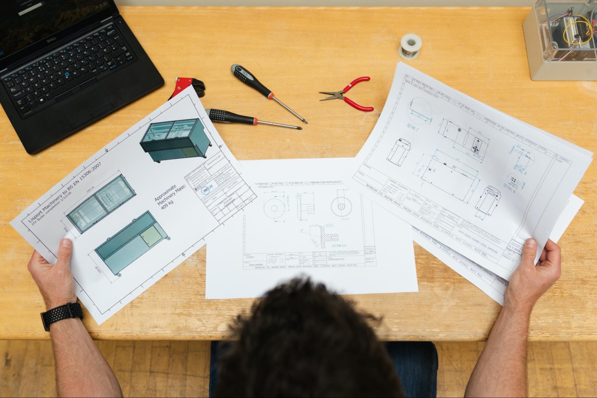
CAD drawings are digital representations or blueprints of designs created using specialized software known as Computer-Aided Design (CAD) software. These drawings are meticulously crafted by architects, engineers, and designers to communicate their ideas and concepts in a detailed and precise manner.
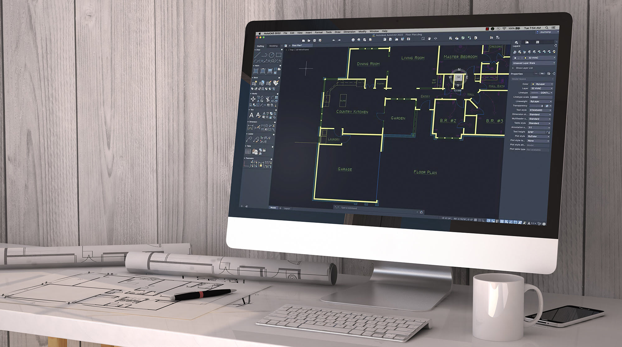
Unlike traditional hand-drawn sketches, CAD drawings are created using a wide range of tools and features that enable designers to manipulate geometry, dimensions, and other design elements with utmost accuracy and efficiency. The software allows for the creation, modification, and optimization of 2D and 3D models, resulting in highly detailed and realistic visualizations of the intended design.
CAD drawings can include various elements such as floor plans, elevations, sections, details, and schedules. They serve as a visual guide for construction teams, enabling them to interpret and bring the design to life accurately. These drawings can also incorporate annotations, dimensions, and annotations, providing essential information to ensure that the design is implemented correctly.
Moreover, CAD drawings are not limited to specific industries or fields. They are widely used in architecture, engineering, construction, manufacturing, interior design, and many other design-related disciplines. From residential buildings and commercial complexes to industrial machinery and product prototypes, CAD drawings are instrumental in every step of the design and development process.
Overall, CAD drawings are the backbone of modern design and construction projects, providing a comprehensive and detailed representation of the intended design. They serve as a visual language that bridges the gap between conceptual ideas and the final realization of a structure or product.
Importance of CAD Drawings
CAD drawings play a pivotal role in the design and construction industry, offering numerous benefits and advantages. Let’s explore why CAD drawings are of utmost importance:
- Precision and Accuracy: CAD software allows designers to create drawings with exceptional precision and accuracy. Measurements can be entered with exact values, ensuring that dimensions are consistent and accurate. This level of precision is crucial in industries where even minor errors can have significant implications.
- Efficiency and Time Savings: CAD drawings streamline the design process by enabling designers to work faster and more efficiently. With tools that automate repetitive tasks, designers can focus on creativity and problem-solving. The ability to make changes easily and quickly also saves valuable time during the design iteration process.
- Visualization and Communication: CAD drawings provide a realistic and detailed visualization of the design, allowing stakeholders to better understand the project. Clients, builders, and other professionals can easily visualize and comprehend the final result, resulting in fewer misunderstandings and improved communication.
- Collaboration and Coordination: CAD drawings facilitate collaboration between different teams and disciplines involved in a project. By sharing digital drawings, stakeholders can coordinate their efforts more effectively, reducing conflicts and ensuring a seamless workflow. This enhances teamwork and improves project outcomes.
- Cost Reduction: CAD drawings help reduce costs by identifying and rectifying design flaws early in the process. This eliminates the need for costly rework and avoids potential construction issues and delays. Additionally, precise material quantities and accurate cost estimations can be derived from CAD drawings, aiding in efficient project budgeting and cost management.
- Flexibility and Adaptability: CAD drawings allow for easy modifications and adaptability as design requirements evolve. Designers can experiment with different ideas, evaluate alternative options, and iterate on the design without starting from scratch. This flexibility ensures that the final design is optimized and meets the client’s expectations.
Overall, CAD drawings have become an invaluable tool in the design and construction industry. With their precision, efficiency, communication capabilities, and cost-saving potentials, CAD drawings enhance the entire design process, leading to better-quality projects and satisfied clients.
Types of CAD Drawings
CAD drawings encompass a wide range of design elements and disciplines, each serving a specific purpose in the design and construction process. Let’s explore some of the common types of CAD drawings:
- Architectural Drawings: These drawings focus on the visual representation and layout of buildings and structures. They include floor plans, elevations, sections, and details that showcase the spatial arrangement, dimensions, and aesthetics of a design. Architectural drawings are crucial for conveying the overall design intent to the construction team.
- Structural Drawings: These drawings provide detailed information about the structural components of a building or structure. They include details on column layouts, beam sizes, foundation plans, and reinforcing details. Structural drawings ensure that the building can withstand the applied loads and maintain its stability and integrity.
- Mechanical Drawings: Mechanical drawings focus on the design of mechanical systems, such as HVAC (heating, ventilation, and air conditioning), plumbing, and electrical systems. These drawings include equipment layouts, piping diagrams, wiring schematics, and equipment specifications. They help coordinate the installation and ensure the smooth operation of mechanical systems.
- Electrical Drawings: Electrical drawings depict the electrical systems within a building or facility. They include the location of electrical outlets, lighting fixtures, wiring diagrams, and panel schedules. Electrical drawings ensure that the electrical installation meets safety standards and efficiently supplies power throughout the building.
- Interior Design Drawings: These drawings focus on the aesthetic and functional aspects of interior spaces. They include furniture layouts, finishes schedules, lighting plans, and millwork details. Interior design drawings assist in visualizing and implementing the chosen design concept, creating cohesive and aesthetically pleasing interiors.
- Landscaping Drawings: Landscaping drawings showcase the design and arrangement of outdoor spaces, including gardens, pathways, water features, and hardscape elements. These drawings highlight the alignment, dimensions, and materials used in the landscape design, providing guidance for installation and maintenance.
These are just a few examples of the many types of CAD drawings used in various industries. Each type serves a different purpose and contributes to the overall success of a design or construction project. The combination of these drawings ensures a comprehensive understanding and execution of the envisioned design.
When creating CAD drawings, be sure to use layers to organize different elements of the design. This will make it easier to manage and edit the drawing as needed.
Creation Process of CAD Drawings
The creation of CAD drawings involves a systematic and meticulous process that combines creativity with technical expertise. Let’s explore the typical steps involved in creating CAD drawings:
- Gather Requirements: The first step is to gather all the necessary information and requirements for the project. This includes understanding the client’s vision, reviewing architectural and engineering plans, and identifying any specific design criteria or constraints.
- Conceptualization and Sketching: Once the requirements are clear, the designer begins the conceptualization phase. Ideas and design concepts are sketched by hand or using digital tools. These initial sketches help refine the design direction and explore different options before moving on to the CAD software.
- Create the Digital Model: With the design concept in mind, the designer starts creating the digital model using CAD software. The software provides a range of tools to draw, edit, and manipulate the design elements. The designer converts the conceptual sketches into 2D or 3D digital models, ensuring accuracy and precision.
- Add Details and Annotations: Once the basic digital model is created, the designer adds details such as dimensions, annotations, and notations. These elements provide essential information about materials, manufacturers, and specific features. Clear and concise annotations ensure that the design can be easily understood and executed by others.
- Review and Iteration: The CAD drawings are then reviewed by the designer, project team, and clients to ensure that they meet the desired design intent and project requirements. Feedback is incorporated, and any necessary changes or modifications are made to the drawings. This iterative process helps refine the design and eliminate any potential errors or issues.
- Finalize the Drawings: Once the design is approved, the CAD drawings are finalized by ensuring that all design elements, annotations, and dimensions are accurate and complete. The drawings are saved in the appropriate file formats and organized in a logical manner for easy access and sharing.
- Sharing and Collaboration: The finalized CAD drawings are shared with relevant stakeholders, including architects, engineers, contractors, and suppliers. Collaboration tools and software facilitate communication and allow for easier coordination between teams.
- Update and Revision: Throughout the project lifecycle, CAD drawings may need to be updated and revised to reflect changes or modifications. As new design information becomes available or as the project progresses, the drawings are updated to ensure they remain accurate and current.
The creation process of CAD drawings involves a combination of creativity, technical skills, and attention to detail. It is a collaborative effort that requires effective communication and coordination among all stakeholders involved in the design and construction process.
Read more: How To Read A CAD Drawing
Applications of CAD Drawings
CAD drawings have a wide range of applications across various industries and disciplines. Let’s explore some of the key areas where CAD drawings are extensively utilized:
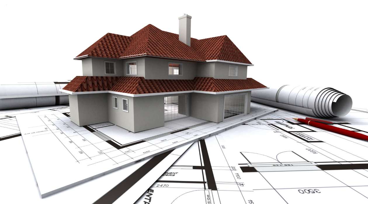
- Architecture and Construction: CAD drawings are vital in architectural design and construction projects. They are used to create detailed floor plans, elevations, and sections, allowing architects and builders to visualize and communicate the design intent accurately. CAD drawings also facilitate coordination between different building disciplines, such as structural and MEP (mechanical, electrical, and plumbing) systems.
- Engineering and Manufacturing: CAD drawings are essential in engineering and manufacturing industries. They enable engineers to design and model complex parts and assemblies, ensuring precise dimensions and clear manufacturing instructions. CAD drawings are also utilized for prototyping, product development, and manufacturing process planning.
- Interior Design: CAD drawings play a crucial role in interior design projects. Designers use them to create furniture layouts, lighting plans, and detailed millwork drawings. CAD drawings help in visualizing spatial arrangements, selecting finishes, and guiding the construction of interior spaces.
- Urban Planning and Landscape Design: CAD drawings are utilized in urban planning to layout and visualize the development of cities and towns. They help in analyzing traffic flow, plotting zoning regulations, and designing public spaces. In landscape design, CAD drawings assist in planning and creating beautiful and functional outdoor spaces.
- Product Design and Prototyping: CAD drawings are widely used in product design and prototyping. They allow designers to create 3D models and visualize how the product will look and function. CAD drawings can be used to test different design concepts, evaluate ergonomics, and generate accurate manufacturing specifications.
- Education and Research: CAD drawings are extensively used in educational institutions for teaching architectural, engineering, and design principles. Students learn to interpret and create CAD drawings as part of their coursework. CAD also plays a significant role in research projects, enabling researchers to model and analyze complex systems and phenomena.
These are just a few examples of the many applications of CAD drawings. From large-scale construction projects to small-scale product designs, CAD drawings are integral to the design, planning, and execution of various projects in today’s digital age. Their versatility and accuracy make them indispensable tools for professionals across multiple industries.
Advantages and Limitations of CAD Drawings
CAD drawings offer numerous advantages that have revolutionized the design and construction industry. However, they also have certain limitations. Let’s examine both the advantages and limitations of CAD drawings:
Advantages of CAD Drawings:
- Precision and Accuracy: CAD drawings allow for precise and accurate measurements, ensuring that design elements fit together correctly and reducing errors during the construction phase.
- Efficiency and Productivity: CAD software automates repetitive design tasks, increasing efficiency and productivity. Designers can focus their time and effort on creativity and problem-solving rather than manual drafting.
- Visualization and Communication: CAD drawings provide realistic visual representations, allowing stakeholders to better understand and visualize the design. They facilitate effective communication among designers, clients, and construction teams.
- Collaboration and Coordination: CAD drawings enable seamless collaboration and coordination between various disciplines involved in a project. Different teams can work simultaneously on different aspects of the design, reducing conflicts and ensuring a smooth workflow.
- Flexibility and Iteration: CAD drawings are easily modifiable, allowing designers to experiment with different design options, make changes on-the-fly, and iterate on the design. This flexibility empowers designers to optimize the design and explore alternative solutions more efficiently.
- Cost Savings: CAD drawings can help identify and rectify design flaws early in the process, avoiding costly rework during construction. Accurate material quantities and cost estimations derived from CAD drawings aid in cost management and budgeting.
Limitations of CAD Drawings:
- Technical Expertise Required: Working with CAD software requires specialized technical skills and knowledge. Designers and engineers need to be proficient in using the software effectively, which may require training and experience.
- Initial Investment and Infrastructure: Implementing CAD software and hardware can involve a significant initial investment for businesses. They need to purchase software licenses, computers with suitable specifications, and ensure a reliable IT infrastructure to support CAD operations.
- Learning Curve: Learning to use CAD software proficiently takes time and effort. Designers need to become familiar with the software’s features, tools, and workflows, which can slow down the design process initially.
- Design Limitations: CAD software has its limitations in terms of the complexity and types of designs it can handle. Certain intricate designs or organic shapes may be challenging to create using CAD, requiring alternative design methods or software.
- Dependence on Software: CAD drawings are reliant on the software being used. Software compatibility issues, version updates, or changes in software availability can pose challenges in accessing and modifying CAD drawings in the future.
- Loss of Personal Touch: As CAD drawings are digitally generated, some may argue that they lack the personal touch and artistry that traditional hand-drawn sketches possess.
Despite these limitations, the advantages of CAD drawings far outweigh the drawbacks. They have become an essential tool in the design and construction industry, revolutionizing the way designs are created, visualized, and communicated.
Conclusion
CAD drawings have become an integral part of the design and construction industry, providing designers and engineers with powerful tools to bring their ideas to life. These digital representations offer precision, accuracy, and efficiency, enhancing the entire design process from conceptualization to construction.
Throughout this article, we have explored the definition of CAD drawings, their importance, types, creation process, applications, and advantages and limitations. We have seen how CAD drawings revolutionize architecture, engineering, and design, making the visualization and communication of complex ideas easier than ever before.
The precision and accuracy of CAD drawings ensure that designs are executed with utmost precision, minimizing errors and avoiding costly rework. The efficiency and productivity gains of CAD software allow designers to focus on creativity and problem-solving, streamlining the design process and reducing project timelines.
CAD drawings facilitate effective communication and collaboration among project stakeholders, allowing for seamless coordination between different disciplines. They enable visualizations that aid in better decision-making, resulting in improved outcomes and client satisfaction.
Despite the advantages of CAD drawings, they do have limitations, such as the initial investment required, the need for specialized technical skills, and the dependence on software. However, these limitations can be mitigated with proper training, infrastructure investment, and staying updated with industry trends and advancements.
In conclusion, CAD drawings have transformed the way designs are created, visualized, and executed. They have revolutionized the design and construction industry, offering precision, efficiency, and enhanced collaboration. CAD drawings continue to push the boundaries of design, enabling architects, engineers, and designers to turn their visions into reality.
Frequently Asked Questions about What Are CAD Drawings
Was this page helpful?
At Storables.com, we guarantee accurate and reliable information. Our content, validated by Expert Board Contributors, is crafted following stringent Editorial Policies. We're committed to providing you with well-researched, expert-backed insights for all your informational needs.


0 thoughts on “What Are CAD Drawings”