Home>diy>Building & Construction>How To Read Construction Site Plans
Building & Construction
How To Read Construction Site Plans
Modified: February 25, 2024
Learn how to read construction site plans and understand the different elements involved in building construction.
(Many of the links in this article redirect to a specific reviewed product. Your purchase of these products through affiliate links helps to generate commission for Storables.com, at no extra cost. Learn more)
Introduction
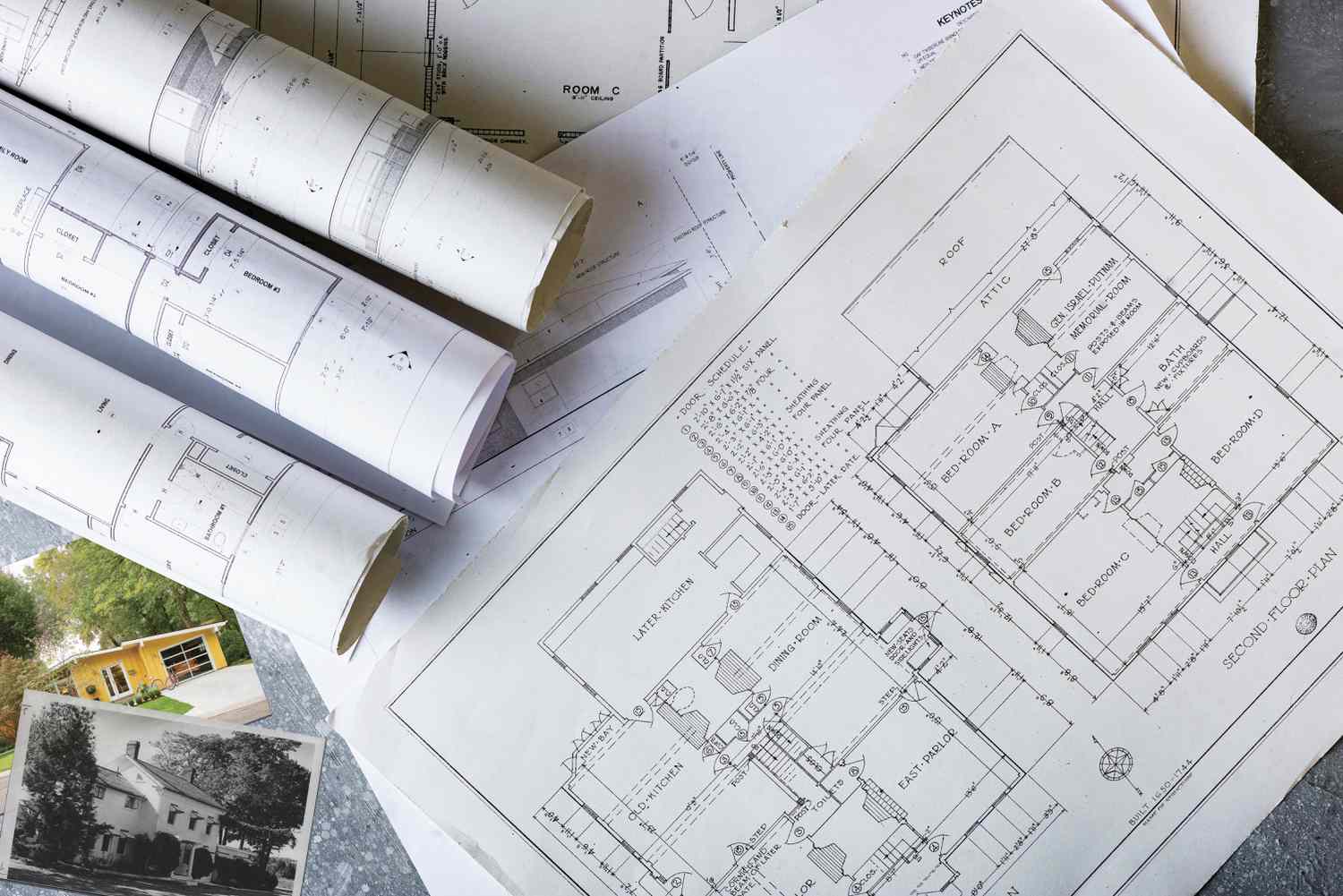
Construction site plans, also known as construction drawings or blueprints, are essential documents that provide a detailed representation of a building project. These plans act as a communication tool between the architects, engineers, contractors, and other professionals involved in the construction process. They outline the various aspects of the project, including the layout, dimensions, materials, and systems that will be implemented.
Understanding construction site plans is crucial for anyone involved in the construction industry, from architects and engineers to contractors and project managers. These plans provide vital information about the project, allowing stakeholders to visualize and interpret the design intent of the building. By comprehending construction site plans, professionals can effectively collaborate, make informed decisions, and ensure that the project meets all necessary requirements.
In this article, we will delve into the intricacies of construction site plans and explore how to read them effectively. We will examine the key elements of these plans, decipher symbols and abbreviations, and discuss the various types of plans commonly encountered in construction projects. By the end of this article, you will have a solid understanding of how to navigate through construction site plans and extract the necessary information to successfully execute a building project.
So, whether you’re new to the construction industry or looking to expand your knowledge, let’s dive in and unravel the mysteries of construction site plans together.
Key Takeaways:
- Understanding construction site plans is crucial for effective collaboration and informed decision-making in the construction industry. By decoding symbols, analyzing floor plans, and reviewing utilities, stakeholders can ensure successful project execution.
- Construction site plans provide a comprehensive representation of building projects, encompassing site layout, floor plans, elevations, and infrastructure. Mastering the art of reading these plans is essential for professionals to visualize design intent and ensure compliance.
Read more: What Is A Site Plan In Construction
Understanding Construction Site Plans
Before we delve into the intricacies of reading construction site plans, it is important to understand their purpose and significance in the construction process. Construction site plans serve as a visual representation of a building project and provide detailed information about its design, layout, and specifications. These plans are typically created by architects and engineers and are used by contractors, builders, and other professionals involved in the construction process.
Construction site plans are comprehensive documents that encompass various aspects of a building project. They include detailed drawings, dimensions, and specifications for the site layout, floor plans, elevations, sections, and utilities. These plans are crucial for ensuring the accurate execution of the project and maintaining consistency among all involved parties.
By understanding construction site plans, professionals can effectively communicate and interpret the design intent of the project. This enables them to coordinate their efforts and ensure that the construction process proceeds smoothly and efficiently. Additionally, construction site plans serve as a reference throughout the entire project, providing guidance and information for decision-making, troubleshooting, and compliance with building codes and regulations.
When examining construction site plans, it is important to keep in mind that they are not static documents. Construction projects evolve, and plans may undergo revisions and updates as design changes are made or new information becomes available. As such, it is essential to refer to the most current version of the plans and stay informed about any updates that may affect the construction process.
Now that we understand the significance of construction site plans, let’s explore the key elements that make up these complex documents.
Key Elements of Construction Site Plans
Construction site plans are composed of various key elements that provide essential information about the building project. Understanding these elements is crucial for accurately interpreting and navigating through the plans. Let’s take a closer look at each of these elements:
Title Block: The title block is typically located in the lower right-hand corner of the construction site plan. It contains important project information such as the project name, address, scale, date of the drawing, and the name of the architect or engineer who created the plan. The title block serves as a reference point for identifying the plan and its context within the overall project.
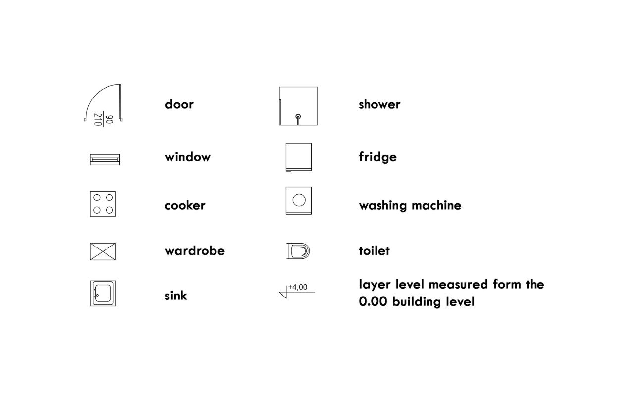
Symbols and Abbreviations: Construction site plans utilize symbols and abbreviations to represent various elements, features, and materials used in the project. These symbols and abbreviations are typically listed in a legend, which provides a key for decoding the meaning of the symbols throughout the plan. Understanding these symbols is crucial for accurately interpreting the design intent and specifications of the project.
Site Layout Plan: The site layout plan provides an overview of the entire construction site and its surroundings. It includes details such as property boundaries, access roads, parking areas, landscaping, and other site-specific features. This plan helps stakeholders visualize how the building will fit into the site and its relationship to neighboring structures.
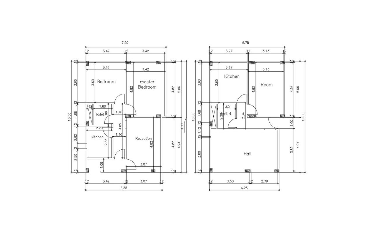
Floor Plans: Floor plans depict the layout and dimensions of each floor of the building. They provide information on room sizes, wall locations, door and window placements, and other architectural details. Floor plans help stakeholders understand the flow and functionality of the building’s spaces and how different areas relate to one another.
Elevations and Sections: Elevations are drawings that show the vertical view of the building’s exterior walls, indicating the height, width, and specific architectural features. Sections, on the other hand, provide a detailed cross-section view of the building, showing the internal structure, wall assemblies, and other construction details. Elevations and sections help stakeholders understand the building’s exterior appearance and the various construction elements within it.
Utilities and Infrastructure: Construction site plans also include information about utilities and infrastructure, such as electrical, plumbing, and HVAC systems. These plans show the routing, connections, and specifications for these essential components, ensuring that they are properly integrated into the building’s design.
Understanding these key elements of construction site plans is crucial for accurately interpreting and extracting the necessary information for a successful construction project. By familiarizing yourself with these elements and their significance, you will be better equipped to navigate through the complex world of construction site plans. Now, let’s move on to the next step: reading the title block.
Reading the Title Block
The title block is an essential element of a construction site plan as it contains important project information that helps identify and understand the plan. By carefully examining the title block, you can gather crucial details about the project. Let’s take a closer look at the key information typically found in a title block:
Project Name: The project name is usually located at the top of the title block and provides a unique identifier for the construction site plan. It is typically a concise and descriptive name that represents the project’s purpose or location. For example, it may include the name of the building, site, or development.
Address: The address is an important piece of information that identifies the specific location of the project. It includes the street name, city, state, and zip code. This information is crucial for locating the project and ensuring accuracy in documentation.
Scale: The scale indicates the relationship between the measurements on the plan and their corresponding real-world dimensions. It is represented as a ratio or a graphic scale. The scale helps stakeholders understand the relative sizes and proportions of various elements within the plan and enables accurate measurements and calculations.
Date of the Drawing: The date of the drawing specifies when the construction site plan was created or revised. It allows stakeholders to track the timeline of the project and identify the most current version of the plan. It is essential to refer to the most up-to-date drawing to ensure accuracy and alignment with any recent changes.
Architect/Engineer: The name of the architect or engineer who created the construction site plan is typically included in the title block. This information provides important attribution and allows stakeholders to contact the responsible party for further inquiries or clarifications.
By understanding and analyzing the information presented in the title block, you can gain valuable insights into the project’s identity, location, and timeline. This information acts as a reference point for further analysis and interpretation of the construction site plan. Now that we have explored the title block, let’s move on to decoding symbols and abbreviations.
Decoding Symbols and Abbreviations
Construction site plans utilize a wide range of symbols and abbreviations to represent various elements, features, and materials involved in the project. These symbols and abbreviations are condensed visual representations that convey specific information in a concise manner. Understanding and decoding these symbols and abbreviations is crucial for accurately interpreting the design intent and specifications of a construction site plan. Let’s explore some common symbols and abbreviations and their meanings:
Door Symbol: Doors are often represented by a rectangle with a line in the middle. The direction of the line indicates whether the door opens inward or outward. The symbol may also include additional markings to indicate swing direction and door type (e.g., sliding, revolving).
Window Symbol: Windows are typically depicted as squares or rectangles with diagonal lines representing the glass panes. The symbol may include additional markings to indicate the type of window (e.g., sliding, casement) and the dimensions of the window opening.
Electrical Outlets and Switches: Electrical outlets are commonly indicated by a small circle, while light switches are represented by a small square. The symbol may include additional markings to specify the type of outlet or switch (e.g., duplex outlet, three-way switch) and their precise locations.
Plumbing Fixtures: Plumbing fixtures such as sinks, toilets, and showers are usually represented by specific symbols. For example, a circle with a dot in the center may represent a sink, while a circle with a triangle pointing downward may represent a toilet.
Material Key: A material key or legend is typically included in the construction site plan to explain the meaning of symbols and abbreviations specific to the project. This key provides a comprehensive list of symbols and abbreviations used in the plan and their corresponding materials or elements.
Abbreviations: Construction site plans also employ various abbreviations to convey information in a succinct manner. Common abbreviations include “BR” for bedroom, “Bth” for bathroom, “Rm” for room, “HVAC” for heating, ventilation, and air conditioning, and “N” for north.
It is important to refer to the legend or material key provided in the construction site plan to understand the precise meaning behind each symbol and abbreviation. The legend provides valuable information about the materials, features, and systems represented in the plan, ensuring accurate interpretation and implementation of the design.
By familiarizing yourself with common symbols and abbreviations and consistently referring to the legend, you will be able to decode and understand the information presented in a construction site plan more effectively. Next, let’s move on to interpreting the legend.
Read more: What Is A Construction Site
Interpreting the Legend
The legend, also known as the material key, is an integral part of a construction site plan. It provides a comprehensive guide to the symbols and abbreviations used throughout the plan, helping stakeholders interpret and understand the various elements and features represented. Let’s explore the importance of the legend and how to effectively interpret it:
Understanding Construction Site Plans: Interpreting the Legend.
The legend is typically located on one corner of the construction site plan, and it consists of a list of symbols, abbreviations, and their corresponding meanings. The legend serves as a reference tool, allowing stakeholders to quickly identify and comprehend the information represented by each symbol or abbreviation. By referring to the legend, one can gain detailed insights into the design intent, materials, and systems embedded in the plan.
The legend is organized in a structured manner, with symbols grouped together based on their category or function. For example, symbols representing doors, windows, or electrical fixtures may be grouped under the corresponding sections. This layout makes it easier to navigate and locate specific symbols or abbreviations within the legend.
When interpreting the legend, it is essential to pay attention to the context of each symbol or abbreviation. Consider the specific project and its requirements to ensure accurate interpretation. Some symbols or abbreviations may have project-specific meanings or correspond to specific materials or equipment unique to that project. It is crucial to familiarize yourself with these project-specific variations to avoid any misinterpretation.
The legend may also include additional information, such as color codes or shading patterns, to further enhance the understanding of the construction site plan. These visual cues provide additional details about the intended materials, finishes, or design elements represented in the plan. By carefully examining these additional indicators, stakeholders can gain a more comprehensive understanding of the project.
It is important to note that the legend may differ slightly between different construction site plans. While there are standard symbols and abbreviations used across the industry, there may be variations based on regional practices, building codes, or individual project requirements. Always refer to the specific legend provided with the construction site plan to ensure accurate interpretation.
By effectively interpreting the legend, stakeholders can decode the symbols and abbreviations used in the construction site plan, gaining a clear understanding of the design intent, materials, and systems depicted. This comprehension is vital for accurate implementation of the project and effective communication among all stakeholders involved.
Now that we have explored how to interpret the legend, let’s move on to examining the site layout plan and its significance in a construction site plan.
When reading construction site plans, always start by familiarizing yourself with the key or legend to understand the symbols and abbreviations used on the plan. This will help you interpret the information accurately.
Examining the Site Layout Plan
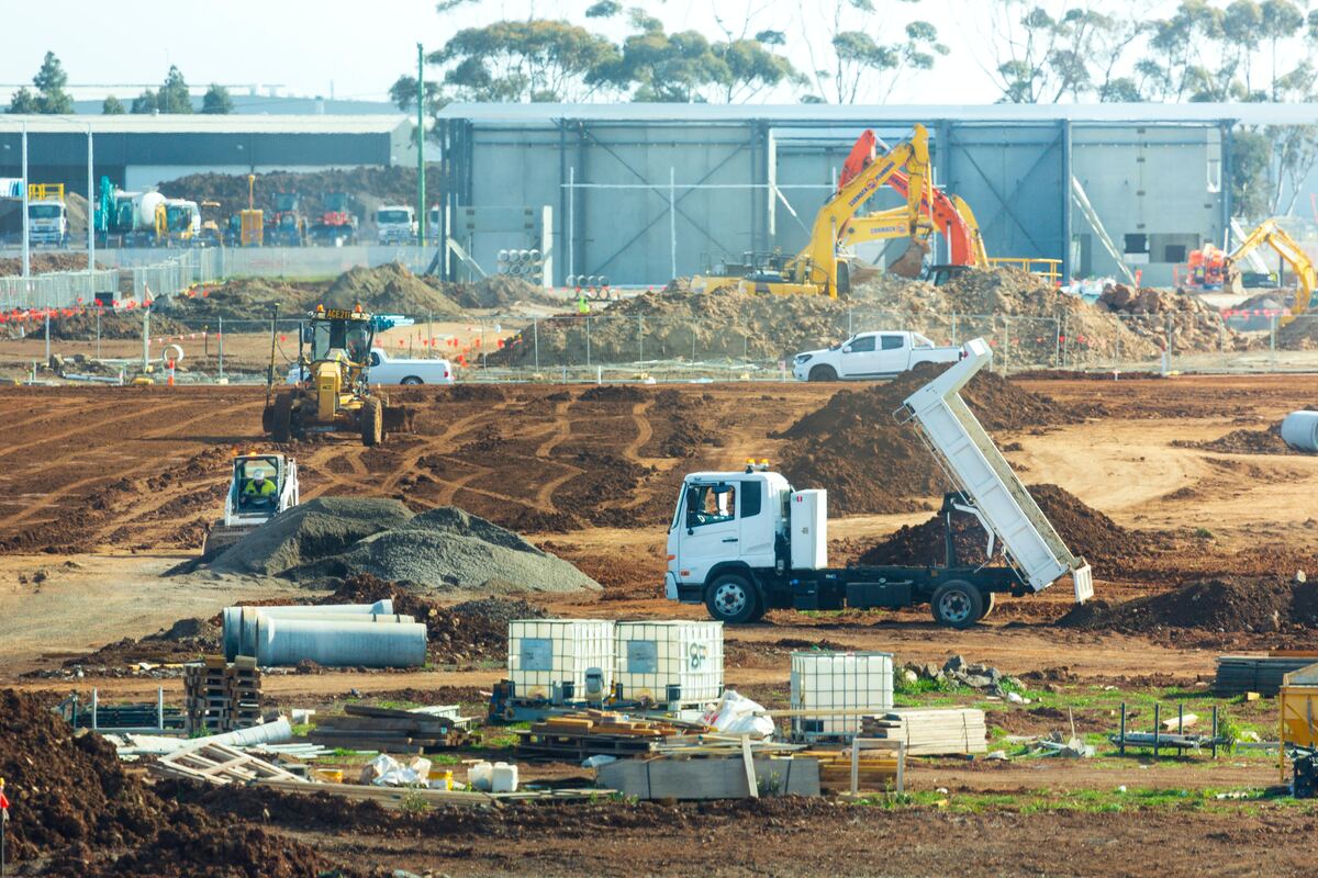
The site layout plan is an essential component of a construction site plan as it provides a visual representation of the entire construction site and its surroundings. This plan illustrates the relationships between various site features, such as buildings, roads, landscaping, and utilities. Examining the site layout plan is crucial for understanding the site’s context and the overall project. Let’s explore the key aspects of the site layout plan and its significance:
The site layout plan typically includes information such as:
- Property boundaries: The site layout plan clearly delineates the boundaries of the property on which the construction project is taking place. This information helps stakeholders understand the size and shape of the site.
- Access roads: The plan indicates the location and layout of access roads, driveways, or parking areas associated with the construction site. This information is vital for transportation logistics and site accessibility.
- Building footprint: The site layout plan illustrates the positioning and orientation of the building(s) on the site. It shows the outline of the building footprint, helping stakeholders visualize how the structure fits within the site.
- Landscaping and open spaces: The plan may include landscaping features such as trees, lawns, or garden areas. It also identifies any open spaces or recreational areas within the site. This information provides insights into the aesthetic and functional aspects of the site.
- Utilities and infrastructure: The site layout plan displays the location of utilities, such as water supply lines, sewer lines, electrical connections, or gas lines. It also indicates the placement of infrastructure elements, such as stormwater management systems or underground tanks. Understanding the positioning of these features is essential for proper integration and coordination during the construction process.
- Environmental considerations: The site layout plan may highlight any environmentally sensitive areas within or around the site. This could include wetlands, wildlife habitats, or other protected zones. Identifying these areas helps ensure compliance with environmental regulations and guides construction practices to minimize impact.
Examining the site layout plan provides stakeholders with a holistic view of the project in its context. It helps identify potential challenges or constraints that may arise due to site conditions or surrounding features. For example, a nearby river or steep slope may require specific construction techniques or additional design considerations.
By thoroughly analyzing the site layout plan, stakeholders can make informed decisions regarding site logistics, workflow, and construction sequencing. Understanding the site’s context also aids in identifying potential site improvements or optimizations to enhance efficiency and functionality.
Furthermore, the site layout plan serves as a reference throughout the construction process to ensure that the building aligns with the intended site design. It provides a foundation for subsequent plans, such as floor plans and elevations, and helps stakeholders understand how the building integrates into its surroundings.
Now that we have examined the site layout plan, let’s move on to analyzing the floor plans and their significance in a construction site plan.
Analyzing the Floor Plans
The floor plans are a crucial component of a construction site plan as they provide detailed representations of each floor of the building. These plans illustrate the layout, dimensions, and design elements of each space, helping stakeholders understand the functionality and flow of the building. Analyzing the floor plans is essential for visualizing the project and making informed decisions. Let’s explore the significance of floor plans and how to effectively analyze them:
The floor plans typically include information such as:
- Room layout: The floor plans outline the placement and sizes of each room within the building. This information allows stakeholders to understand the spatial organization and utilization of different areas.
- Wall locations: The floor plans indicate the placement of walls, helping stakeholders visualize the division of spaces and the overall structure of the building. Wall locations play a crucial role in determining the flow and functionality of each room.
- Door and window placements: The floor plans illustrate the positions of doors and windows in each room. This information guides stakeholders in understanding accessibility, natural lighting, and ventilation throughout the building.
- Furniture and fixtures: The floor plans may include symbols or indications for furniture and fixtures such as cabinets, sinks, or appliances. These representations help stakeholders visualize how the space can be furnished or equipped.
- Dimensions: The floor plans provide accurate measurements of the rooms and spaces within the building. This information is crucial for determining clearances, circulation areas, and compliance with building codes and regulations.
- Staircases and elevators: If the building includes multiple levels, the floor plans show the location and design of staircases or elevators. This information is vital for understanding vertical circulation within the building.
By analyzing the floor plans, stakeholders can gain insights into the overall layout and functionality of the building. They can visualize how spaces connect, how natural lighting enters the building, and how occupants will move through the various rooms. Analyzing the floor plans is also essential for evaluating the practicality and suitability of the design for its intended purpose.
Furthermore, examining the floor plans allows stakeholders to identify potential design improvements or modifications. They can assess if rooms are appropriately sized, if circulation paths are efficient, and if the overall design aligns with project requirements. This analysis aids in making informed decisions to optimize the design and enhance the building’s functionality.
In addition, analyzing the floor plans helps stakeholders identify any potential design conflicts or coordination issues. For example, they can check for alignment between electrical outlets and furniture placement, or ensure that HVAC vents are properly positioned in each room. This attention to detail ensures smoother execution during the construction phase.
Overall, the thorough analysis of floor plans enables stakeholders to better understand the spatial organization, flow, and functionality of the building. It helps align the design intent with the construction process and allows for efficient decision-making throughout the project.
Now that we have explored how to analyze the floor plans, let’s move on to understanding elevations and sections in a construction site plan.
Understanding Elevations and Sections
Elevations and sections are vital components of a construction site plan as they provide detailed views of the building’s exterior and interior. Elevations depict the vertical view of the building, while sections provide cross-sectional views. Understanding and analyzing elevations and sections is essential for comprehending the building’s design, structural elements, and construction details. Let’s delve into the significance of elevations and sections and how to effectively interpret them:
Elevations:
Elevations illustrate the building’s exterior appearance and provide a comprehensive view of the vertical surfaces, including walls, doors, windows, and architectural details. They showcase the building from different angles, allowing stakeholders to visualize the overall façade and understand the building’s proportions and aesthetics.
Elevations also provide information about the building’s materials and finishes. They may include notations or symbols to indicate the type of material or texture used for different surfaces. This information helps stakeholders evaluate the building’s visual impact and make decisions regarding material selections or design enhancements.
Sections:
Sections, on the other hand, offer a cut-through view of the building, showing the internal components, structural elements, and construction details. They provide valuable insights into the building’s vertical dimensions, wall assemblies, floor-to-ceiling heights, and the relationships between different levels.
Sections are particularly helpful for evaluating the building’s spatial organization, circulation paths, and the positioning of structural elements such as columns or beams. They allow stakeholders to visualize how the building’s spaces stack on top of each other and identify any potential design issues or conflicts.
Sections also aid in understanding the building’s structural integrity. They provide details on the placement of load-bearing walls, foundations, and other structural elements that ensure the building’s stability and safety. Analyzing these details helps stakeholders assess the structural soundness and compliance with building codes during the construction process.
Effective Interpretation:
When analyzing elevations and sections, it is important to pay attention to the scale, dimensions, and annotations provided in the construction site plan. These details help stakeholders understand the precise measurements, clearances, and relationships between various elements within the building.
It is also crucial to refer to any accompanying notes, symbols, or legends specific to the elevations and sections. These annotations provide additional information about materials, finishes, or construction techniques, further enhancing the understanding of the design intent.
Interpreting elevations and sections requires a multidimensional understanding of the building’s design, materials, and structure. By thoroughly analyzing these views, stakeholders gain a comprehensive understanding of the building’s exterior appearance, internal configuration, and construction intricacies.
Now that we have examined elevations and sections, let’s move on to reviewing utilities and infrastructure in a construction site plan.
Read more: How To Be A Construction Site Supervisor
Reviewing Utilities and Infrastructure
Utilities and infrastructure play a crucial role in any construction project, and reviewing them in a construction site plan is essential for understanding the building’s functional systems and ensuring proper integration. Utilities refer to essential services such as electrical, plumbing, heating, ventilation, and air conditioning (HVAC), while infrastructure encompasses elements such as stormwater management, telecommunications, and gas lines. Let’s explore the significance of reviewing utilities and infrastructure in a construction site plan:
Electrical Systems:
The electrical system includes the distribution of power throughout the building, including outlets, switches, lighting fixtures, and electrical panels. Reviewing the electrical information on the construction site plan helps stakeholders understand the locations of electrical outlets, the placement of switches, and the routing of electrical wiring. It is crucial for ensuring that electrical systems meet safety codes and accommodate the needs of the building’s occupants.
Plumbing Systems:
The plumbing system encompasses the pipes, fixtures, and drainage systems that provide water supply and disposal within the building. Reviewing the plumbing information on the construction site plan helps stakeholders understand the locations of water supply lines, sanitary pipes, and plumbing fixtures such as sinks, toilets, and showers. This understanding is essential for ensuring proper water supply, waste management, and compliance with plumbing codes.
HVAC Systems:
The HVAC system regulates heating, ventilation, and air conditioning within the building. Reviewing the HVAC information on the construction site plan helps stakeholders understand the locations of HVAC units, ductwork, vents, and thermostat controls. This information is crucial for ensuring proper temperature control, air circulation, and energy efficiency in the building. It allows stakeholders to identify any potential conflicts or coordination issues with other building elements.
Utilities Infrastructure:
Utilities infrastructure refers to elements such as stormwater management systems, telecommunication lines, and gas pipes. Reviewing this information on the construction site plan helps stakeholders understand the placement and integration of these systems. It ensures proper drainage, connectivity, and compliance with utility regulations. It also helps identify any potential conflicts or coordination issues with other site features or building components.
Reviewing utilities and infrastructure in a construction site plan is crucial for ensuring the functional efficiency, safety, and compliance of the building. By thoroughly examining this information, stakeholders can identify any potential conflicts, clarify design intent, and make informed decisions regarding the placement, integration, and coordination of these systems.
Now that we have reviewed utilities and infrastructure, we have gained a comprehensive understanding of the construction site plan. Let’s summarize the key insights from this article.
Conclusion
Construction site plans are vital documents that provide a detailed representation of a building project. Understanding how to read and analyze these plans is crucial for anyone involved in the construction industry. Throughout this article, we have explored the key elements of construction site plans and discussed how to interpret them effectively.
We began by emphasizing the importance of understanding the purpose and significance of construction site plans. These plans serve as a communication tool and provide vital information about the project’s design, layout, and specifications. By comprehending construction site plans, professionals can collaborate effectively, make informed decisions, and ensure compliance with regulations.
We then delved into the key elements of construction site plans. We explored the title block and its role in identifying the plan, decoding symbols and abbreviations, and interpreting the legend. These elements are necessary for accurately understanding the information presented in the plan.
Next, we discussed the significance of examining the site layout plan. This plan provides a comprehensive overview of the construction site and its surroundings, including property boundaries, access roads, landscaping, and utilities. Understanding the site layout plan helps stakeholders visualize the context of the project and make informed decisions regarding site logistics and functionality.
We moved on to analyzing the floor plans, which provide detailed representations of each floor of the building. These plans help stakeholders understand the layout, dimensions, and design elements of each space. By analyzing the floor plans, stakeholders can visualize the flow, functionality, and spatial organization of the building.
We then explored elevations and sections, which offer detailed views of the building’s exterior and interior. Elevations allow stakeholders to visualiz e the building’s façade and materials, while sections provide insights into the internal components, structural elements, and construction details. Understanding these views helps stakeholders evaluate the building’s design, aesthetics, and structural integrity.
Lastly, we discussed the importance of reviewing utilities and infrastructure in a construction site plan. Utilities, such as electrical, plumbing, and HVAC systems, play a vital role in the functionality of the building. Reviewing the placement and integration of these systems ensures compliance with regulations and functional efficiency.
In conclusion, mastering the art of reading construction site plans is a valuable skill for professionals in the construction industry. By understanding the key elements, decoding symbols and abbreviations, and analyzing the various components of the plan, stakeholders can effectively interpret the design intent, make informed decisions, and ensure successful execution of the building project. So, let’s continue exploring the fascinating world of construction site plans, and apply our knowledge to create remarkable structures.
Frequently Asked Questions about How To Read Construction Site Plans
Was this page helpful?
At Storables.com, we guarantee accurate and reliable information. Our content, validated by Expert Board Contributors, is crafted following stringent Editorial Policies. We're committed to providing you with well-researched, expert-backed insights for all your informational needs.


0 thoughts on “How To Read Construction Site Plans”