Home>diy>Building & Construction>How To Read Construction Blueprints

Building & Construction
How To Read Construction Blueprints
Modified: December 7, 2023
Learn how to read construction blueprints and gain a deeper understanding of building construction techniques with our comprehensive guide.
(Many of the links in this article redirect to a specific reviewed product. Your purchase of these products through affiliate links helps to generate commission for Storables.com, at no extra cost. Learn more)
Introduction
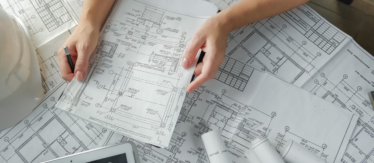
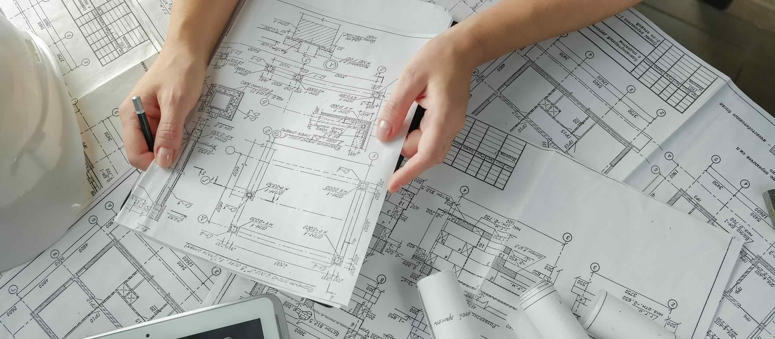
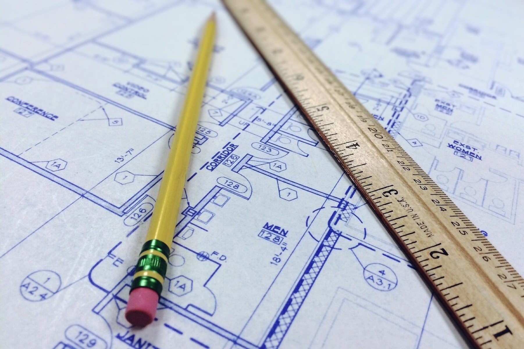
Welcome to the fascinating world of construction blueprints! In the realm of building construction, blueprints serve as the guiding light for architects, engineers, and construction professionals. These meticulously detailed documents provide a roadmap for creating structures, from towering skyscrapers to cozy homes. Whether you’re a budding engineer or just curious about how buildings come to life, understanding how to read construction blueprints is an essential skill.
In this article, we will delve into the intricacies of construction blueprints and unravel the secrets hidden within these technical drawings. We will explore how to decipher architectural drawings, interpret structural plans, analyze electrical layouts, decode plumbing diagrams, identify HVAC systems, recognize fire protection layouts, and even explore landscape design plans. By the end, you’ll have a comprehensive understanding of the various components that make up a construction blueprint.
Reading construction blueprints may seem intimidating at first with the abundance of symbols, abbreviations, and technical language. However, with a little guidance, you’ll soon find yourself navigating through these intricate documents with confidence. Whether you’re a professional in the construction industry looking to sharpen your skills or an aspiring DIY enthusiast eager to take on home improvement projects, this article will equip you with the knowledge and understanding to unlock the secrets of construction blueprints.
So, fasten your hardhat and grab your magnifying glass as we embark on a journey to unravel the mysteries of construction blueprints. Let’s dive in and discover the fascinating world of architectural drawings, structural plans, electrical layouts, plumbing diagrams, HVAC systems, fire protection layouts, and landscape design plans.
Key Takeaways:
- Understanding construction blueprints is essential for professionals and DIY enthusiasts alike, enabling effective communication, informed decision-making, and the successful execution of construction projects.
- From architectural drawings to landscape design plans, decoding construction blueprints unlocks the secrets of building construction, empowering individuals to shape the built environment with creativity and expertise.
Read more: How To Read An Electrical Blueprint
Understanding Construction Blueprints
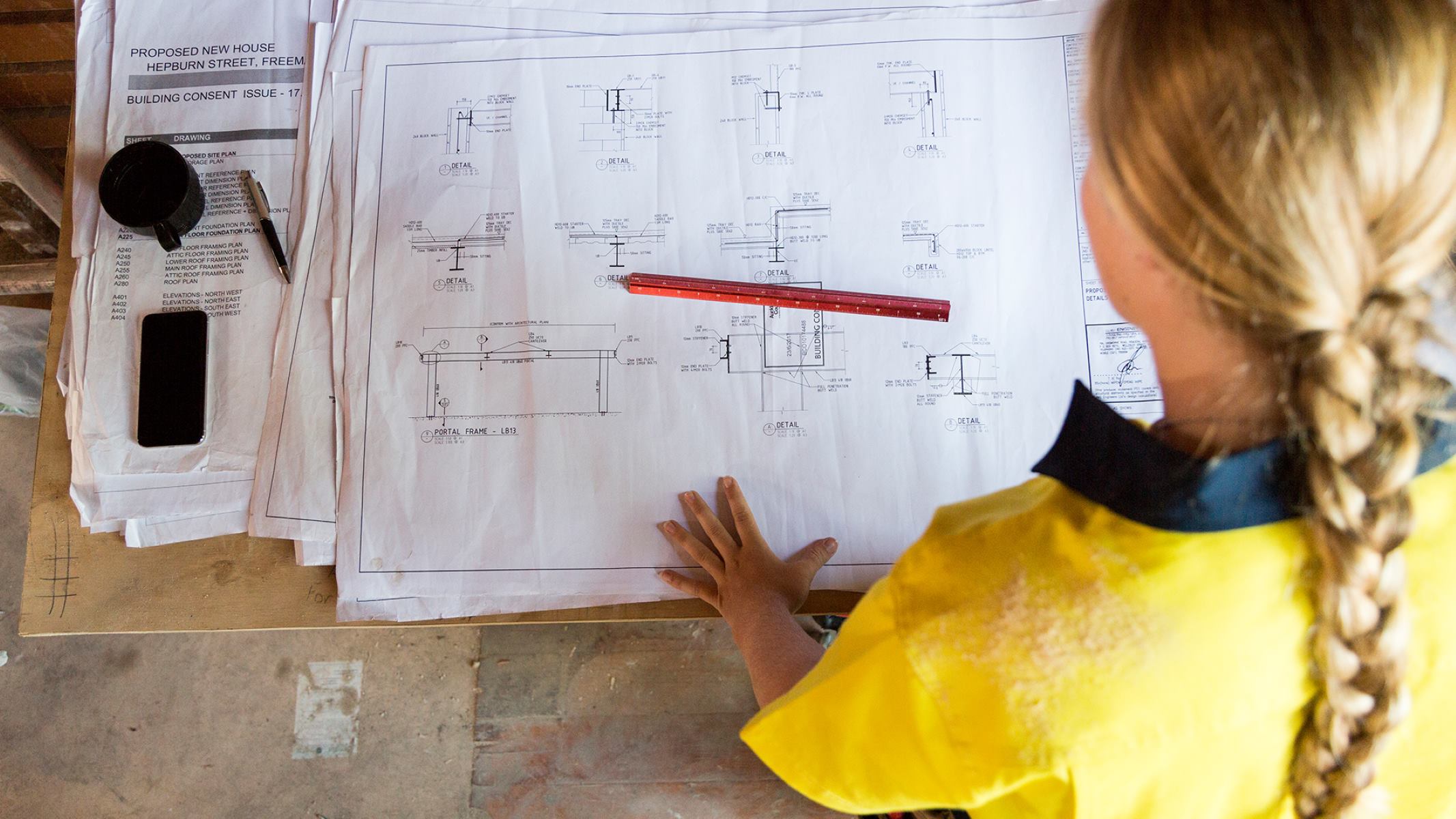
Construction blueprints, also known as construction plans or drawings, are visual representations that outline the design, dimensions, and specifications of a building or structure. They provide a detailed overview of the project, serving as a communication tool between architects, engineers, contractors, and other professionals involved in the construction process.
Blueprints are highly detailed and meticulously prepared documents that encompass various aspects of the building, including architectural, structural, electrical, plumbing, and mechanical systems. These plans are essential for ensuring that the construction is executed accurately and in accordance with the intended design.
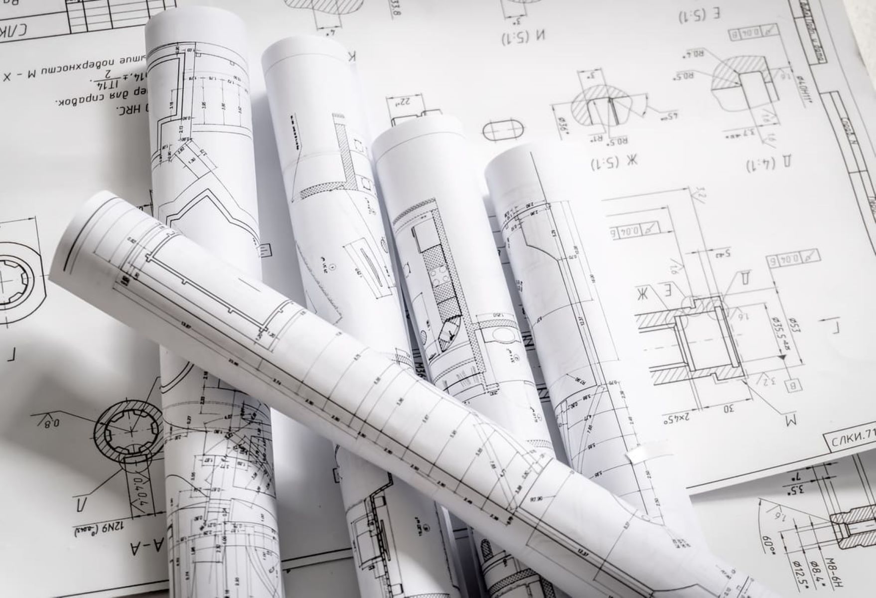
Blueprints typically consist of multiple sheets or pages, each focusing on specific aspects of the project. They are usually drawn to scale, providing accurate measurements and proportional representation of the building components.
Understanding construction blueprints requires familiarity with common symbols, abbreviations, and conventions used in the industry. Architects and engineers use these symbols to convey information about different elements such as walls, doors, windows, electrical fixtures, plumbing fixtures, and mechanical systems.
Furthermore, blueprints include detailed notes, dimensions, and specifications that provide additional information about materials, construction methods, and specific requirements. These annotations are crucial for ensuring that the contractors and construction workers follow the intended design and meet the necessary standards.
Construction blueprints serve as a central reference point throughout the entire construction process. Contractors and workers refer to the blueprints to understand the layout of the building, determine the placement of various components, and ensure the accurate execution of the design.
By understanding construction blueprints, you gain insight into the inner workings of a building and the critical components that make it functional and safe. With this knowledge, you can effectively communicate with professionals in the construction industry, make informed decisions during a project, and even undertake small-scale construction projects on your own.
In the next sections of this article, we will explore the intricacies of various types of construction blueprints, including architectural drawings, structural plans, electrical layouts, plumbing diagrams, HVAC systems, fire protection layouts, and landscape design plans. Let’s continue our journey by diving into the fascinating world of architectural drawings.
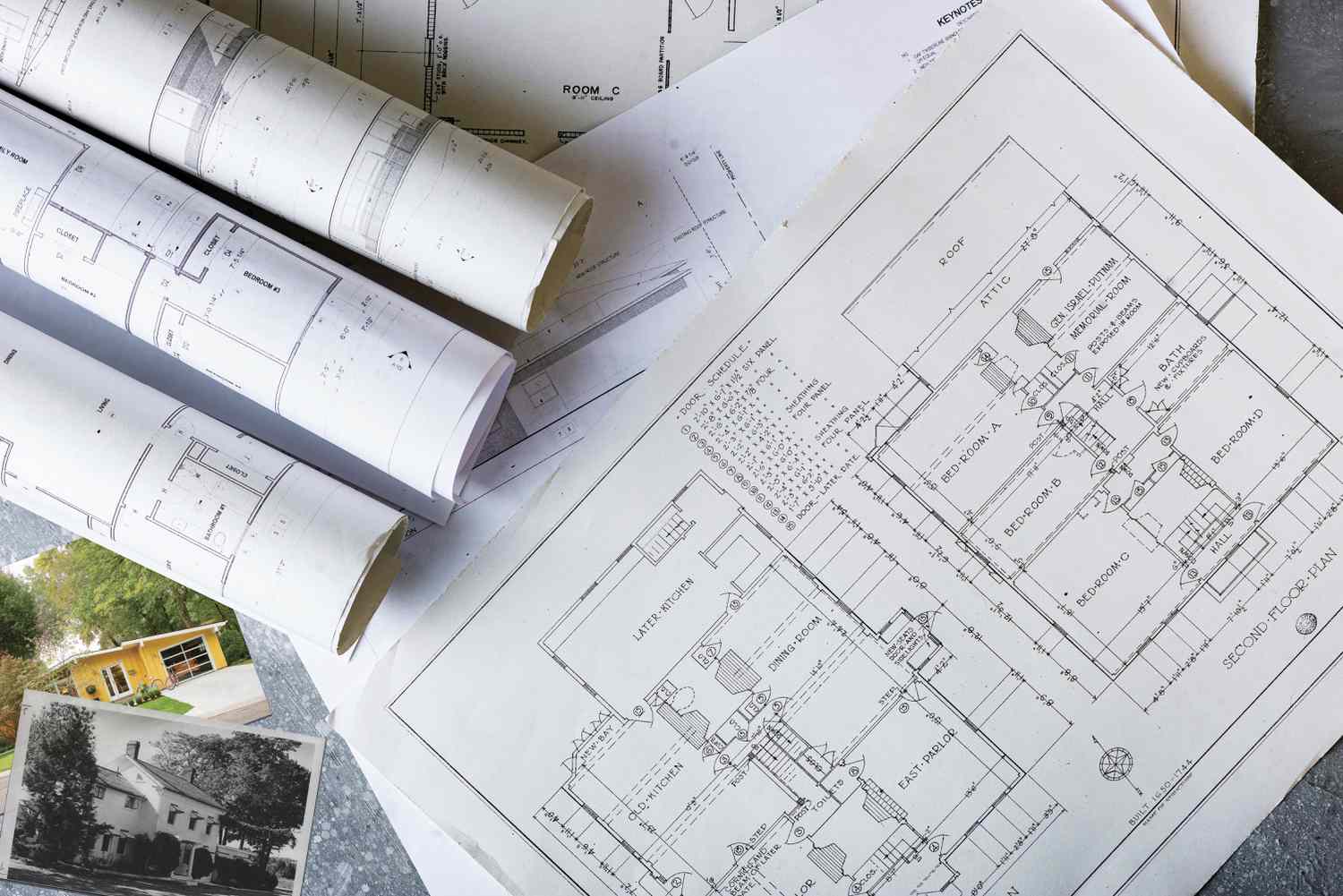
Reading Architectural Drawings
Architectural drawings are a crucial component of construction blueprints. They provide a visual representation of the building’s design and layout, showcasing the arrangement of rooms, walls, windows, and other architectural elements. By understanding architectural drawings, you can gain insight into the overall structure and aesthetics of the building.
When reading architectural drawings, it’s important to familiarize yourself with some common elements and symbols:
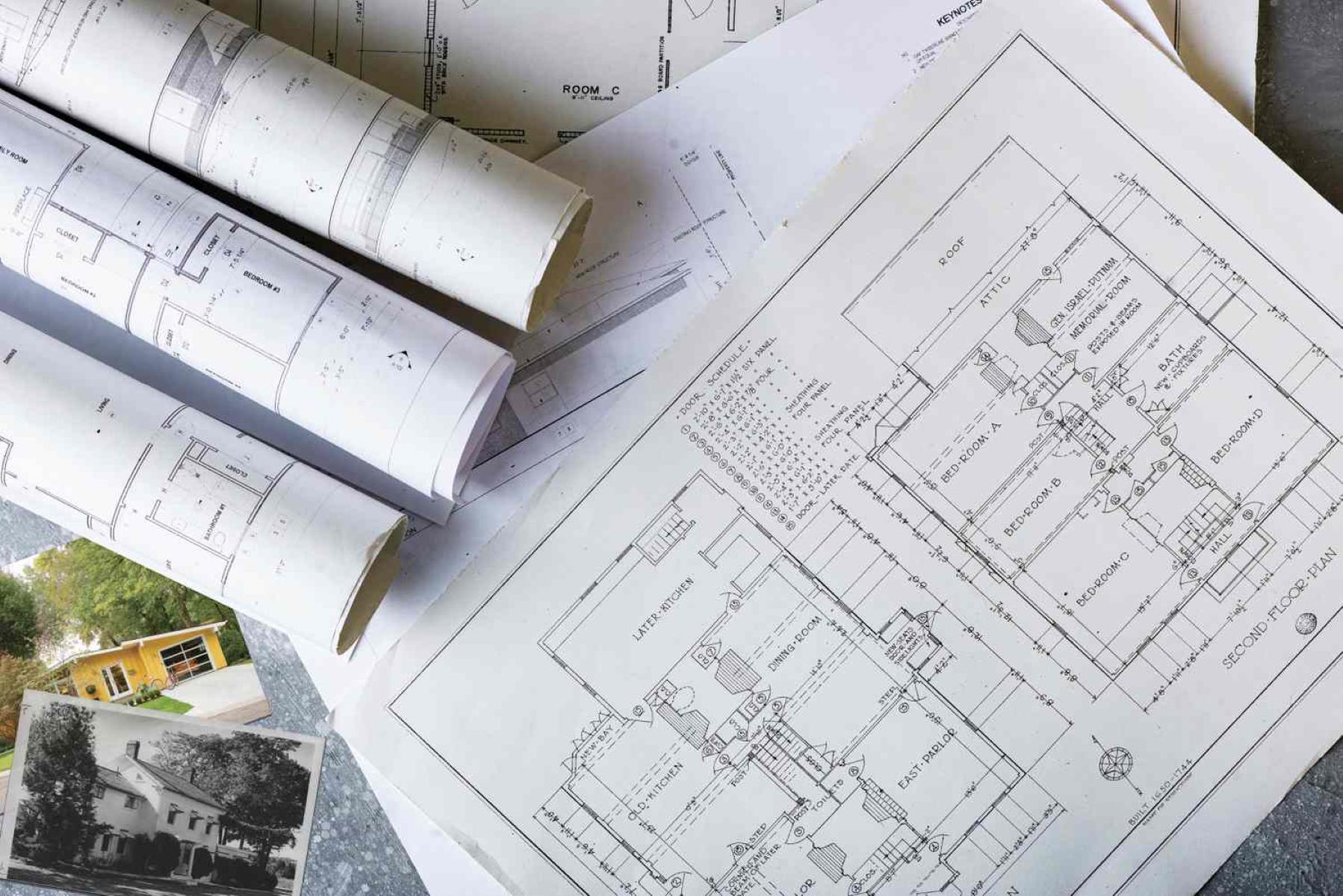
- Floor Plan: The floor plan is a horizontal cut-through view of the building at a specific level, illustrating the layout of rooms, walls, doors, and windows. It provides a bird’s-eye view of the building’s interior and serves as a guide for understanding the spatial organization.
- Elevations: Elevations are drawings that show the exterior views of the building from different angles. They provide a detailed view of the building’s facade, showcasing the size and proportions of windows, doors, and architectural features.
- Section Drawings: Section drawings cut through the building to reveal the internal structure. They showcase the vertical view of the building, allowing you to understand the relationship between different floors and sections.
- Symbol Key: Architectural drawings often include a symbol key or legend that explains the meaning of different symbols and abbreviations used in the drawings. This key is essential for decoding the various elements in the plans.
When interpreting architectural drawings, it’s crucial to pay attention to the scales and measurements provided. Scales indicate the ratio between the drawing and the actual building dimensions. By understanding the scale, you can determine the size and proportions of various elements.
Additionally, architectural drawings often include annotations and dimensions that provide critical information about the layout and design intent. These dimensions help determine the size of rooms, the height of ceilings, and the placement of architectural features.
Understanding architectural drawings empowers you to visualize the building’s design and layout, making it easier to communicate with architects, contractors, and other professionals involved in the construction process. It allows you to identify potential design issues, suggest modifications, and ensure that the final structure aligns with your vision.
Next, we will delve into the realm of structural drawings, which provide essential information about the building’s framework and load-bearing elements. Join me as we explore the intricate world of construction blueprints!
Interpreting Structural Drawings
When it comes to construction blueprints, structural drawings play a vital role in ensuring the strength, stability, and integrity of a building. These drawings provide detailed information about the structural framework, load-bearing elements, and the overall stability of the building.
Interpreting structural drawings requires an understanding of key elements and symbols commonly found in these plans:
- Foundation Plan: The foundation plan illustrates the layout and dimensions of the building’s foundation. It shows the placement of footings, columns, and other supporting structures that distribute the weight of the building to the ground.
- Beams and Columns: Structural drawings depict the location, size, and type of beams and columns that carry the load of the building. They indicate the material and dimensions required for these elements to ensure stability and safety.
- Structural Details: Structural drawings include detailed sections and details that highlight specific areas such as connections, reinforcement, and the placement of structural elements. These details are crucial for proper construction and maintaining the structural integrity of the building.
- Load Calculations: Structural drawings may include load calculations that determine the weights and forces the building is designed to withstand. These calculations help engineers ensure that the structure can safely bear its intended loads.
Understanding structural drawings is vital for architects, engineers, and contractors involved in the construction process. It allows them to accurately implement the structural design, ensure compliance with building codes and regulations, and maintain the safety and stability of the building.
When interpreting structural drawings, it’s essential to carefully review the dimensions and specifications provided. This includes the size and type of materials to be used, reinforcement requirements, and any specific instructions related to construction techniques.
Structural drawings often work in conjunction with architectural drawings, as they depict how the structural elements align with the overall design of the building. This collaboration between architectural and structural plans ensures that the aesthetics and functionality of the building are harmoniously integrated.
By understanding and interpreting structural drawings, you gain insight into the foundation and framework of the building, allowing you to assess its strength, stability, and overall structural integrity. Whether you’re an architect seeking to create innovative designs, an engineer analyzing the structural feasibility, or a contractor responsible for the physical construction, the ability to interpret these drawings is paramount.
Next, we will explore the world of electrical plans and the importance of understanding them in the context of construction blueprints. Join me as we unravel the intricate details of building construction!
Analyzing Electrical Plans
Electricity is the lifeblood of any modern building, and electrical plans are a key component of construction blueprints. These plans provide a detailed representation of the electrical systems, wiring, and equipment that power the building. Analyzing electrical plans is crucial to ensure the safety, functionality, and efficiency of the electrical infrastructure.
When examining electrical plans, it’s important to familiarize yourself with the symbols and components commonly used:
- Electrical Legend: The electrical legend or symbol key provides a comprehensive list of symbols used on the electrical plans. These symbols represent various electrical components, such as outlets, switches, lights, and circuit breakers.
- Power Distribution: The electrical plan highlights the distribution of power throughout the building. It shows the location of the main electrical panel, subpanels, and distribution boards, along with the corresponding circuitry.
- Lighting Layout: The lighting layout showcases the placement and type of lighting fixtures throughout the building. It includes information on the types of bulbs or lamps to be used and provides the necessary wiring details.
- Switching Circuits: Electrical plans depict the connection of switches to control lights, fans, and other devices. These circuits provide information on how the electrical components are interconnected and operated.
- Circuit Loads: Assess the electrical load calculations, which determine the capacity needed to power various devices and equipment throughout the building. Understanding the load requirements helps in determining the appropriate size of wires, circuit breakers, and distribution panels.
- Outlet Placement: Evaluate the placement of electrical outlets for convenience and functionality. Ensure that outlets are strategically located in areas where they are needed, such as near workstations, kitchen countertops, and living spaces.
- Safety Measures: Pay attention to the inclusion of safety devices such as ground-fault circuit interrupters (GFCIs) and arc-fault circuit interrupters (AFCIs) to protect against electrical shocks and fires.
- Emergency Power: Analyze provisions for emergency power systems, including backup generators, uninterruptible power supply (UPS) systems, and emergency lighting, to ensure the building remains functional during power outages.
- Water Supply Lines: Plumbing diagrams outline the distribution of water supply lines throughout the building. These lines connect the main water source to individual fixtures, such as sinks, toilets, showers, and washing machines.
- Drainage System: The plumbing plans depict the layout of the drainage system, including waste pipes, vents, and sanitary drainage lines. These elements ensure the proper removal of wastewater from fixtures and prevent sewer gas from entering the building.
- Fixture Locations: Plumbing diagrams indicate the placement of fixtures, such as toilets, sinks, bathtubs, and water heaters. Proper positioning of fixtures is essential for efficient plumbing operation and ease of use.
- Valves and Controls: The diagrams identify valves and control devices that regulate water flow and shut off the water supply. These include shut-off valves, water pressure regulators, and backflow prevention devices.
- Code Compliance: Verify that the plumbing system design adheres to local plumbing codes and regulations. This ensures safety, water efficiency, and compliance with plumbing standards.
- Proper Venting: Check the inclusion of vent pipes that facilitate the release of sewer gases, prevent traps from being siphoned, and maintain proper drainage functionality.
- Water Conservation: Evaluate the incorporation of water-saving fixtures, such as low-flow toilets and faucets, as well as the use of rainwater harvesting or greywater systems, to promote water conservation.
- Accessibility: Consider the accessibility of plumbing components for maintenance, repairs, and future upgrades. Adequate access points help to diagnose and fix plumbing issues efficiently.
- Heating Systems: The blueprints show the type of heating system used, such as furnaces, boilers, or heat pumps. They also indicate the location of heating equipment and ductwork needed to distribute warm air throughout the building.
- Cooling Systems: Cooling systems, such as air conditioners or heat pumps, are depicted on the blueprints. They outline the placement of cooling units, outdoor condensers, and the distribution of cool air through ductwork or other methods.
- Ventilation Systems: The blueprints illustrate the ventilation system, including the placement of intake vents, exhaust fans, and ductwork. Ventilation systems ensure the exchange of fresh air and the removal of stale air and contaminants from the building.
- Ductwork: HVAC plans identify the layout and design of ductwork, which channels conditioned air throughout the building. The blueprints show the route of ducts, sizes, and types of ducts used, as well as the location of registers or diffusers.
- Zoning: Evaluate if the HVAC system is divided into zones, allowing for individual temperature control in different areas of the building. Zoning can improve energy efficiency by directing conditioned air where it’s needed most.
- Energy Efficiency Measures: Look for energy-saving features and equipment, such as programmable thermostats, variable speed motors, and insulation, which enhance the overall energy efficiency of the HVAC system.
- Air Quality Considerations: Assess the inclusion of air filtration systems, humidity control devices, and air purifiers to maintain high indoor air quality and promote occupant health and comfort.
- Accessibility and Maintenance: Consider how accessible the HVAC components are for maintenance and repairs. Adequate access points ensure that technicians can service the system easily.
- Fire Alarm Systems: The blueprints should clearly indicate the placement of fire alarm devices, such as smoke detectors, heat detectors, and manual fire alarm pull stations. These devices are strategically located throughout the building to detect and alert occupants of a fire in its early stages.
- Sprinkler Systems: Fire protection layouts outline the location of sprinkler heads and pipe distribution. Sprinkler systems are designed to release water in the event of a fire, controlling the spread of flames and suppressing the fire until emergency responders arrive.
- Fire Extinguishers and Fire Hoses: The blueprints may indicate the placement of fire extinguishers and fire hoses at strategic locations within the building. These fire suppression tools provide a means for occupants to attempt to extinguish small fires or safely evacuate in the event of a larger fire.
- Fire-rated Walls and Doors: Fire protection layouts show the placement of fire-rated walls and doors, which are designed to limit the spread of fire and smoke throughout the building. These elements create fire compartments, allowing occupants to safely evacuate and provide time for emergency responders to mitigate the incident.
- Code Compliance: Verify that the fire protection layouts comply with local fire codes and regulations. This ensures that the building meets the required safety standards and provides adequate protection for occupants.
- Accessibility: Assess the accessibility of fire protection devices, such as fire extinguishers and pull stations, to ensure they are easily identifiable and reachable in an emergency situation.
- Evacuation Routes: Pay attention to the presence of clearly marked evacuation routes and exit signs, which guide occupants to safety during a fire emergency.
- Emergency Lighting: Check for the inclusion of emergency lighting systems that provide illumination during power outages, ensuring safe evacuation pathways and increased visibility for emergency responders.
- Planting Layout: The landscape design plans portray the arrangement and selection of plants, trees, shrubs, and flowers. They outline the location and spacing of plantings, considering factors such as sunlight exposure, growth patterns, and aesthetics.
- Hardscape Features: These plans depict the placement of non-living elements, such as walkways, patios, seating areas, and water features. Hardscape features are strategically positioned to create functional spaces and enhance the visual appeal of the outdoor area.
- Drainage and Irrigation: Landscape plans delineate the drainage and irrigation systems necessary to manage water flow and ensure the health of plants. They include the placement of drainage pipes, rainwater harvesting systems, and irrigation equipment.
- Lighting: The plans may indicate the location of outdoor lighting fixtures, such as path lights, spotlights, and accent lighting. Outdoor lighting enhances safety, highlights architectural features, and creates an inviting ambiance.
- Environmental Considerations: Assess the incorporation of sustainable design elements, such as native plantings, drought-tolerant landscaping, and permeable surfaces, to promote water conservation and environmental stewardship.
- Accessibility: Evaluate the accessibility of outdoor spaces for all individuals, ensuring the presence of pathways and ramps that comply with accessibility guidelines and regulations.
- Site Constraints: Consider any site-specific constraints, such as slopes, easements, or existing trees, that may influence the design and functionality of outdoor spaces.
- Seating and Gathering Areas: Note the provision of seating areas, gathering spaces, and recreational amenities, which create opportunities for socializing, relaxation, and outdoor activities.
Analyzing electrical plans requires attention to detail and an understanding of building codes and electrical regulations. It’s crucial to ensure that the electrical infrastructure meets safety standards and adheres to local electrical codes.
When examining electrical plans, be sure to consider the following:
By analyzing electrical plans, you can ensure that the electrical infrastructure of the building is designed and implemented correctly. Whether you’re an electrical contractor, designer, or building owner, understanding these plans is essential for a safe and functional electrical system.
Next, we will dive into the realm of plumbing diagrams and explore their significance in construction blueprints. Join me as we unravel the hidden network of pipes and fixtures that make up the building’s plumbing system!
When reading construction blueprints, always start by familiarizing yourself with the legend and scale to understand the symbols and measurements used throughout the drawings.
Read more: How To Read A Welding Blueprint
Decoding Plumbing Diagrams
Plumbing diagrams are fundamental components of construction blueprints that provide a detailed representation of the plumbing system within a building. These diagrams illustrate the arrangement of pipes, fixtures, and equipment responsible for supplying water, removing wastewater, and ensuring proper drainage. Decoding plumbing diagrams is crucial for understanding the plumbing infrastructure of a building and ensuring its functionality.
When analyzing plumbing diagrams, it’s essential to familiarize yourself with the symbols and elements commonly used:
Analyzing plumbing diagrams involves considering several factors to ensure a functional and efficient plumbing system:
By decoding plumbing diagrams, you can grasp the intricate network of pipes, fixtures, and equipment that comprise the building’s plumbing system. Understanding these diagrams enables you to communicate effectively with plumbers, contractors, and other professionals involved in the construction process. It also allows you to identify potential issues, suggest modifications, and ensure the plumbing system meets your specific needs.
Next, let’s explore the realm of HVAC systems and learn how to identify and interpret their plans in construction blueprints. Join me as we unravel the complex world of heating, ventilation, and air conditioning!
Identifying HVAC Systems
HVAC (Heating, Ventilation, and Air Conditioning) systems are integral to maintaining comfortable indoor environments in buildings. Identifying HVAC systems within construction blueprints is crucial for understanding the heating, cooling, and ventilation infrastructure of a building. These systems ensure optimal temperature control, air quality, and energy efficiency.
When analyzing blueprints to identify HVAC systems, keep an eye out for the following elements:
Identifying HVAC systems in construction blueprints allows for a better understanding of how the systems integrate into the overall design of the building. It enables proper coordination among architects, engineers, and contractors, ensuring that HVAC systems are appropriately integrated without compromising the aesthetics or functionality of the space.
When analyzing HVAC systems within blueprints, consider the following factors:
By identifying HVAC systems within construction blueprints, you gain insight into the heating, cooling, and ventilation infrastructure of the building. Understanding these systems allows you to effectively communicate with HVAC professionals, assess energy efficiency, and make informed decisions related to comfort and indoor air quality.
Next, we will explore the importance of recognizing fire protection layouts in construction blueprints. Join me as we uncover the critical components of fire safety within a building!
Recognizing Fire Protection Layouts
Fire protection layouts are an essential aspect of construction blueprints, ensuring the safety of occupants and mitigating the risks associated with fire incidents. Recognizing and understanding fire protection layouts within blueprints allows for the effective implementation of fire prevention and suppression measures within a building.
When examining construction blueprints to identify fire protection layouts, pay attention to the following elements:
Recognizing fire protection layouts is crucial for implementing effective fire safety measures within a building. When scrutinizing these layouts, consider the following factors:
By recognizing fire protection layouts within construction blueprints, you gain insight into the essential components of fire safety within a building. Understanding these layouts aids in effective communication with fire protection professionals, ensures compliance with fire codes, and enhances overall occupant safety.
Next, we will explore the significance of landscape design plans within construction blueprints. Join me as we appreciate the beauty and functionality of outdoor spaces!
Exploring Landscape Design Plans
Landscape design plans within construction blueprints are as important as the interior layout and architectural elements of a building. These plans provide a detailed representation of the outdoor areas, including gardens, pathways, hardscape features, and outdoor amenities. Exploring landscape design plans allows for the creation of functional, aesthetic, and environmentally friendly outdoor spaces that enhance the overall building design.
When examining landscape design plans, keep an eye out for the following elements:
Exploring landscape design plans within construction blueprints enables the creation of harmonious outdoor spaces that complement the building’s design and fulfill functional needs. Consider the following factors when analyzing these plans:
By exploring landscape design plans within construction blueprints, you gain insight into the outdoor environment surrounding a building. This understanding allows for the creation of beautiful, functional, and sustainable outdoor spaces that enhance the overall building design and create a seamless connection between the indoor and outdoor areas.
Now that we have explored the various components of construction blueprints, from architectural drawings to landscape design plans, you have gained a comprehensive understanding of how to read construction blueprints. By acquiring this valuable knowledge, you can confidently navigate the intricacies of construction projects and effectively communicate with professionals in the industry.
Remember, construction blueprints are the roadmap to transforming architectural visions into tangible structures. Embrace the power of these technical drawings, and let your creativity and expertise shape the built environment!
Read more: How To Read HVAC Blueprints
Conclusion
Congratulations! You have successfully embarked on a journey into the intricate world of construction blueprints. We have explored the various aspects of reading and understanding these technical drawings, from architectural plans to landscape design layouts. Armed with this knowledge, you can now navigate the complexities of construction projects, communicate effectively with professionals in the industry, and even undertake small-scale projects on your own.
We began by understanding the significance of construction blueprints and their role in guiding architects, engineers, and contractors throughout the construction process. These detailed documents provide a visual representation of the building’s design, dimensions, and specifications, ensuring accurate implementation and compliance with building codes and regulations.
We delved into reading architectural drawings, deciphering floor plans, elevations, and sections. Understanding these drawings allows you to visualize the building’s design, placement of walls, doors, and windows, and gain a comprehensive understanding of the spatial organization within the structure.
We then explored the intricacies of structural drawings, uncovering the placement of beams, columns, and load-bearing elements that ensure the strength and stability of the building. Interpreting these drawings empowers architects, engineers, and contractors to implement the structural design accurately and maintain the overall integrity of the structure.
Analyzing electrical plans enabled us to grasp the distribution of power throughout the building, identify lighting fixtures and switch circuits, and ensure the functionality and safety of the electrical system. Understanding these plans is crucial for effective communication with electricians and contractors involved in the construction process.
Decoding plumbing diagrams unveiled the complex network of pipes, fixtures, and equipment that comprise the building’s plumbing system. Recognizing these layouts allows for the efficient supply of water and proper disposal of wastewater, ensuring the functionality and convenience of the plumbing infrastructure.
Identifying HVAC systems enabled us to understand the heating, ventilation, and air conditioning infrastructure within a building. This knowledge aids in creating comfortable indoor environments, promoting energy efficiency, and ensuring proper air circulation and quality.
Recognizing fire protection layouts shed light on the crucial components of fire safety within a building. Understanding these layouts allows for the implementation of fire prevention measures, effective detection and alert systems, and proper evacuation protocols to safeguard occupants and protect the building.
Exploring landscape design plans uncovered the beauty and functionality of outdoor spaces. Understanding these plans enables the creation of harmonious and sustainable landscapes that complement the building’s design and enhance the overall user experience.
By immersing ourselves in the realm of construction blueprints, we have unlocked the secrets hidden within these technical documents. Armed with this knowledge, you are now equipped to confidently navigate the world of building construction, collaborate with professionals in the industry, and bring architectural visions to life.
Remember, construction blueprints are not just lines on paper; they are the foundation upon which buildings are built. Embrace their power, inspire creativity, and contribute to the development of safe, functional, and breathtaking structures. The possibilities are endless!
Frequently Asked Questions about How To Read Construction Blueprints
Was this page helpful?
At Storables.com, we guarantee accurate and reliable information. Our content, validated by Expert Board Contributors, is crafted following stringent Editorial Policies. We're committed to providing you with well-researched, expert-backed insights for all your informational needs.


0 thoughts on “How To Read Construction Blueprints”