Home>diy>Architecture & Design>How To Read An Electrical Blueprint
Architecture & Design
How To Read An Electrical Blueprint
Modified: January 9, 2024
Learn how to read an electrical blueprint and gain valuable insights into architecture design with this comprehensive guide.
(Many of the links in this article redirect to a specific reviewed product. Your purchase of these products through affiliate links helps to generate commission for Storables.com, at no extra cost. Learn more)
Introduction
Welcome to the fascinating world of electrical blueprints! If you have ever looked at an electrical blueprint and wondered what all those symbols and lines mean, this article is for you. Understanding how to read an electrical blueprint is an essential skill for anyone involved in the architecture, engineering, and construction industries. Whether you are a professional electrician, an aspiring designer, or simply curious about how buildings are powered, this guide will provide you with the knowledge you need to decipher those complex diagrams.
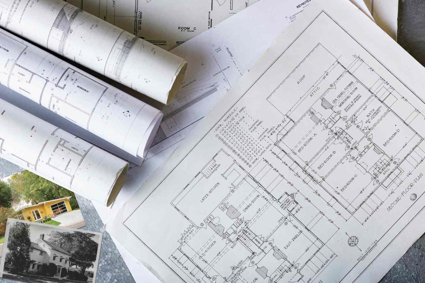
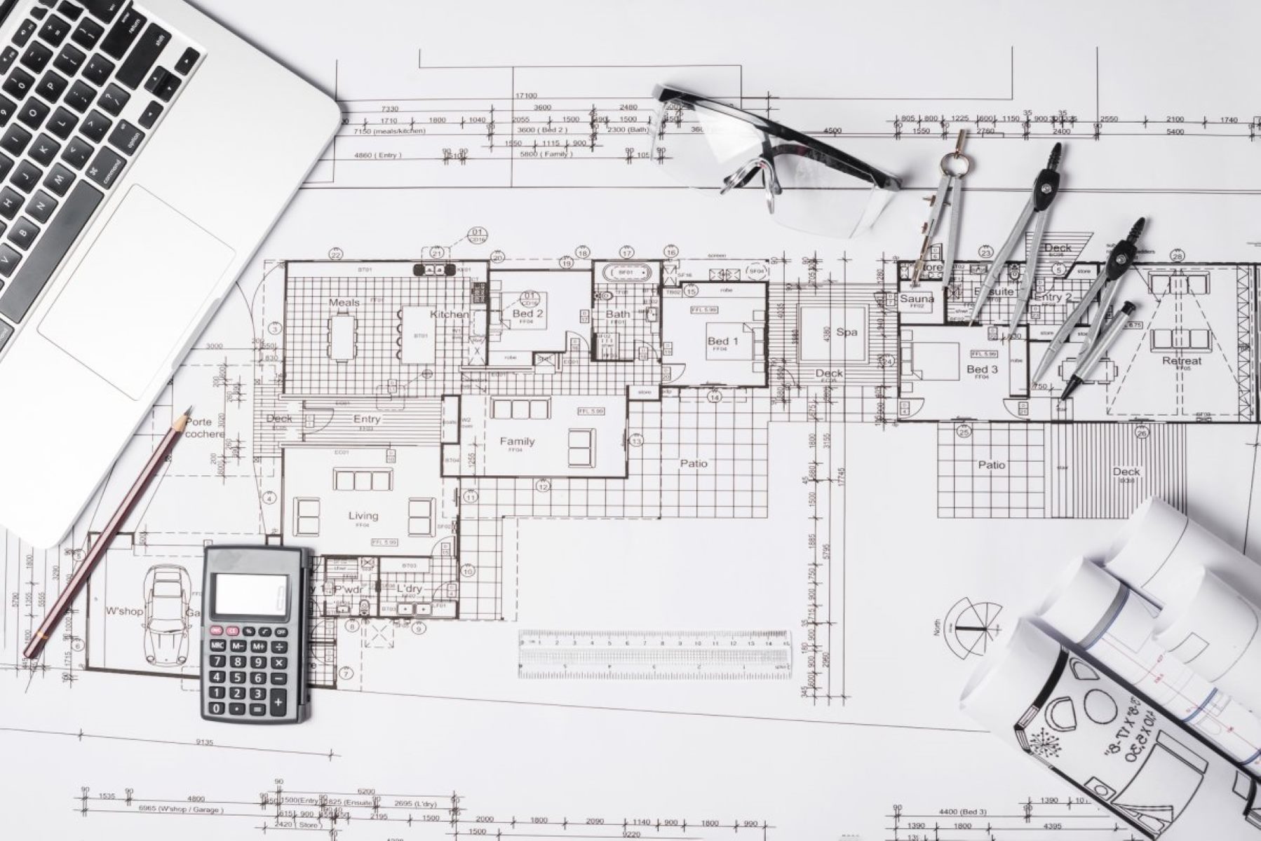
Electrical blueprints, also known as electrical plans, are detailed drawings that show the electrical systems and components within a building. These drawings are a crucial part of the construction process, as they provide a roadmap for installing and configuring the electrical infrastructure.
At first glance, electrical blueprints may appear daunting. The multitude of lines, symbols, and labels can be overwhelming. However, by breaking down the blueprint into smaller sections and understanding the underlying principles, you can start unraveling the mystery and gain confidence in reading these technical documents.
In this article, we will explore the fundamentals of reading an electrical blueprint. We will discuss common symbols and their meanings, as well as how to identify different components and wiring. We will also delve into reading circuit diagrams, interpreting electrical schematics, and analyzing electrical plans. By the end of this guide, you will have a solid understanding of how to follow circuit paths, read panel and control diagrams, and identify troubleshooting points.
Whether you are an electrician working in the field, an architect designing a new building, or a homeowner wanting to better understand your electrical system, this article will equip you with the skills to navigate through electrical blueprints with confidence and precision.
Key Takeaways:
- Mastering the art of reading electrical blueprints and diagrams empowers individuals in architecture, engineering, and construction, enabling confident navigation of complex electrical systems.
- Attention to detail, knowledge of industry standards, and effective communication with professionals are key to successfully interpreting electrical diagrams and ensuring safe and efficient operation.
Read more: How To Read A Welding Blueprint
Understanding Electrical Symbols
One of the first steps in reading an electrical blueprint is to familiarize yourself with the various symbols used to represent different electrical components and devices. These symbols are standardized and universally recognized across the industry, allowing for clear and consistent communication between designers, electricians, and contractors.
Electrical symbols are graphical representations of electrical and electronic devices, such as switches, outlets, lights, and motors. They are used to indicate the presence or function of a specific component within the electrical system. Each symbol has a unique shape and design that provides essential information about the component it represents.
Here are some common electrical symbols you may encounter:
- Switch: The switch symbol represents a device that can open or close an electrical circuit. It is typically depicted as a line interrupted by a gap, with a small vertical line branching off to indicate the position of the switch.
- Outlet: The outlet symbol represents a point where electrical power can be accessed. It typically looks like a circle with two or three prongs, depending on the type of outlet (e.g., standard, GFCI, or USB).
- Light Fixture: The light fixture symbol represents a lighting device, such as a ceiling light or a lamp. It is usually shown as a circle or oval with lines extending upwards to indicate the presence of bulbs or lights.
- Meter: The meter symbol represents a device used to measure electrical quantities, such as voltage, current, or power. It is often depicted as a rectangle with various markings or dials to indicate different measurement parameters.
- Transformer: The transformer symbol is used to represent a device that changes the voltage level of an electrical circuit. It is typically shown as two parallel lines with a circle in the middle, indicating the primary and secondary windings.
- Motor: The motor symbol represents an electric motor that converts electrical energy into mechanical energy. It is usually depicted as a circle with a curved line or several lines extending from it to indicate the rotational motion.
These are just a few examples of the many electrical symbols used in blueprints. It is essential to refer to the blueprint legend or key provided alongside the drawings to understand the specific meanings of each symbol in the context of the project.
By learning and understanding these symbols, you can quickly identify the different components and devices represented in the electrical blueprint. This knowledge forms a solid foundation for reading and interpreting more complex diagrams and plans.
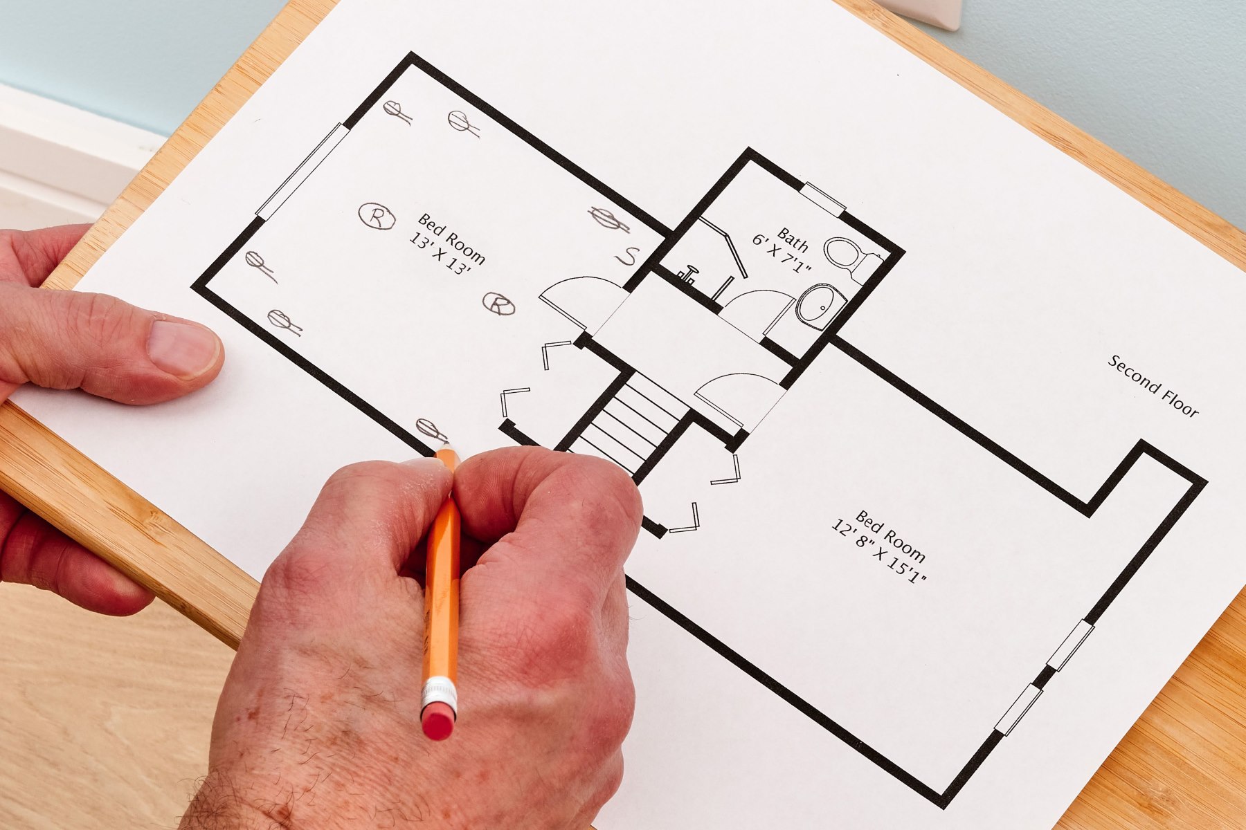
Identifying Components and Wiring
Once you are familiar with the electrical symbols used in blueprints, the next step is to identify the various components and their wiring within the diagram. Understanding how components are connected and the paths of electrical wiring is crucial for visualizing the flow of electricity throughout the system.
Here are some key components and their corresponding wiring you may encounter:
- Switches and Outlets: Switches are commonly found in electrical blueprints and are used to control the flow of electricity to lights, appliances, or other electrical devices. Outlets, on the other hand, provide points of access for electrical power. In the blueprint, switches are typically connected to lights or appliances via electrical wiring lines, while outlets are connected to the main electrical panel or power source.
- Lights and Fixtures: Lighting fixtures, such as ceiling lights or wall sconces, are important components within an electrical system. In the blueprint, lights are typically represented by a symbol and connected to switches through electrical wiring lines. The path of the wiring lines will indicate the flow of electricity from the switch to the fixture.
- Motors and Control Panels: In more complex electrical systems, you may encounter motors and control panels. Motors are electrical devices that convert electrical energy to mechanical energy, while control panels provide a centralized location for controlling and monitoring various functions of the system. Motors are often represented by symbols and connected to control panels via wiring lines.
- Service and Distribution Panels: Service panels, also known as electrical panels or breaker boxes, are crucial components of an electrical system. They distribute electrical power to different circuits throughout the building. In the blueprint, service panels are depicted as boxes with multiple switches or breakers. Wiring lines will indicate the connections between the panel and various circuits.
- Circuit Breakers and Fuses: Circuit breakers and fuses are safety devices that protect the electrical system from overloads or short circuits. In the blueprint, they are represented by symbol and connected to the respective circuits through wiring lines. The path of the wiring lines will show how the breakers or fuses are connected to specific devices or areas.
- Grounding and Bonding: Grounding and bonding are essential for electrical safety and protection against electrical shocks. In the blueprint, ground symbols and wiring lines will indicate the grounding connections for various components, such as outlets, lights, and panels.
By carefully studying the components and their wiring connections within the electrical blueprint, you can gain a clear understanding of how electricity flows through the system. This knowledge will not only help you read the blueprint more efficiently but also enable you to identify potential issues or modifications that may be required for a successful electrical installation.
It is important to note that the complexity of the wiring and the number of components in an electrical blueprint may vary depending on the size and purpose of the building. Always refer to the legend or key provided to ensure accurate interpretation.
Reading Circuit Diagrams
Circuit diagrams, also known as schematics, are a graphical representation of an electrical circuit. They provide a detailed illustration of the components and their interconnections, helping to understand the functionality and operation of the circuit.
When reading circuit diagrams, here are some important elements to consider:
- Components and Symbols: Like in electrical blueprints, circuit diagrams also use standardized symbols to represent various components. These symbols are essential for identifying and understanding the different elements within the circuit diagram. Components such as resistors, capacitors, diodes, transistors, and integrated circuits are represented using specific symbols that convey their properties and functions.
- Lines and Connections: Circuit diagrams use lines to represent the connections between components. These lines indicate the flow of current from one component to another. The direction of the arrow on the line shows the direction of the current flow. It is crucial to follow the lines and connections to understand the logical flow of the circuit.
- Power Supply: The power supply in a circuit diagram represents the source of electrical energy for the circuit. It is typically shown as a battery symbol or as a rectangle with positive and negative terminals, depending on the type of power supply being used. Understanding the power supply is essential for knowing the voltage levels and polarity within the circuit.
- Grounding: Grounding is an important aspect of circuit diagrams as it establishes a reference point for voltage levels. Ground symbols, usually shown as a horizontal line with a triangle, indicate the connection to the earth or a common ground. Grounding is crucial for safety and proper functioning of the circuit.
- Connections and Junctions: In circuit diagrams, you may come across connection points and junctions where multiple lines intersect or come together. These points indicate a connection or a join between components. Understanding the connections and junctions is crucial for determining how various components are linked within the circuit.
- Labels and Notes: Circuit diagrams often include labels and notes to provide additional information about specific components or the circuit as a whole. These labels and notes help in understanding the purpose, values, or characteristics of certain elements within the circuit.
Reading circuit diagrams requires careful observation and attention to detail. It is important to follow the lines, understand the symbols, and analyze the connections to visualize the pathway of current flow and the overall system operation. Circuit diagrams are commonly used in various areas, including electronics, industrial automation, and control systems.
By developing proficiency in reading circuit diagrams, you will be able to troubleshoot and analyze electrical circuits more effectively, making it an invaluable skill in both professional and DIY electrical projects.
Interpreting Electrical Schematics
Electrical schematics go beyond basic circuit diagrams by providing a more comprehensive representation of electrical systems. They offer a detailed view of the interconnections and functions of components within a larger system, allowing for a thorough understanding of its operation.
When interpreting electrical schematics, here are some key factors to consider:
- System Overview: Electrical schematics provide an overview of the entire system, highlighting the major components and their relationships. This allows you to understand the overall structure and organization of the electrical system.
- Modularity: Electrical schematics often emphasize the modularity of the system by dividing it into logical sections or sub-circuits. This helps in understanding the functional units and how they interact with each other.
- Signal Flow: Schematics depict the flow of signals within the system, including electrical currents, voltages, and control signals. By analyzing the signal paths, you can understand how information or power is transmitted between different components and subsystems.
- Control Logic: Electrical schematics often include control logic, which shows the relationship between inputs and outputs and the associated logic operations. This helps in understanding how the system responds to different inputs and performs specific functions.
- Sensors and Actuators: Schematics highlight the sensors and actuators within the system, which are responsible for gathering data and initiating actions, respectively. Understanding the connections and functions of these components is crucial for troubleshooting and fine-tuning the system.
- Power Distribution: Electrical schematics illustrate the distribution of power within the system, including the sources of power and how it is distributed to different components. This helps in understanding the power requirements and ensuring proper functioning of the system.
Interpreting electrical schematics requires a systematic approach. Begin by familiarizing yourself with the overall structure and layout of the schematic. Identify the key components, their connections, and the signal flow paths. Pay close attention to the control logic and any input-output relationships that are illustrated.
One important aspect of interpreting electrical schematics is being able to mentally “zoom in” and “zoom out” to understand the system at different levels of detail. This allows you to grasp the big picture while also diving into specific sections or sub-circuits when needed.
Electrical schematics are commonly used in various industries, including manufacturing, automation, and control systems. They provide a comprehensive and detailed representation of complex electrical systems, aiding in system design, troubleshooting, and maintenance.
By developing the skill to interpret electrical schematics, you will be able to understand the inner workings of advanced electrical systems and make informed decisions to optimize their performance.
When reading an electrical blueprint, start by identifying the key components such as switches, outlets, and lighting fixtures. Then, follow the lines to understand how they are connected and the flow of electricity throughout the building.
Read more: How To Read Construction Blueprints
Analyzing Electrical Plans
Electrical plans are an integral part of architectural and construction drawings, providing a detailed representation of the electrical layout for a building or structure. Analyzing electrical plans involves understanding the placement and organization of electrical components, circuits, and systems within the overall design.
Here are some key factors to consider when analyzing electrical plans:
- Location of Components: Electrical plans indicate the specific locations where electrical components, such as switches, outlets, lights, and panels, will be installed. Understanding the placement of these components is crucial for efficient and effective electrical installations.
- Circuit Layout: Electrical plans depict the layout of electrical circuits throughout the building. This includes the routing of electrical wiring, the distribution of circuit breakers or fuses, and the connections to various electrical components. Analyzing the circuit layout enables you to visualize the flow of electricity and ensure proper distribution and connectivity.
- Load Calculation: Electrical plans often include load calculations, which determine the total electrical load required for each circuit or area of the building. These calculations take into account the power requirements of different appliances and equipment to ensure that the electrical system can handle the expected load demand.
- Symbols and Legend: Electrical plans use standardized symbols to represent different electrical components and systems. It is important to refer to the legend or key provided with the plans to accurately interpret the symbols and understand their meanings within the context of the specific project.
- Code Compliance: Electrical plans must comply with local building codes and regulations. Analyzing the plans involves ensuring that the design meets the required safety and electrical standards, such as the proper placement of outlets, adherence to clearance requirements, and adequate grounding.
- Integration with Other Systems: Electrical plans need to be analyzed in conjunction with other building systems, such as HVAC (heating, ventilation, and air conditioning) or plumbing. This integration ensures that electrical components are properly coordinated with other systems and that potential conflicts or overlaps are identified and resolved.
By carefully analyzing electrical plans, you can identify any potential design issues or discrepancies before the actual installation begins. It allows for proper coordination with other trades involved in the construction process, ensuring a seamless integration and smooth workflow.
It is important to work closely with architects, engineers, and electricians to review and refine the electrical plans. This collaborative approach helps ensure a functional and safe electrical system that meets the specific needs of the building and its occupants.
Analyzing electrical plans requires attention to detail, knowledge of electrical codes and standards, and a thorough understanding of electrical systems. When done effectively, it sets the foundation for a successful electrical installation and operation of the building.
Following Circuit Paths
When it comes to understanding electrical systems, following circuit paths is a fundamental skill. It involves tracing the flow of electricity through various components, connections, and conductors to comprehend how the circuit functions and troubleshoot any issues that may arise.
Here are some key steps to effectively follow circuit paths:
- Identify the Power Source: Start by locating the power source, such as the main electrical panel or a specific circuit. This will give you a starting point for following the flow of electricity.
- Understand the Wiring Layout: Examine the electrical system’s wiring layout, including the connections and routes taken by the electrical conductors. This will help you visualize how the electricity is distributed throughout the circuit.
- Analyze the Components: Take note of the different electrical components present in the circuit, such as switches, outlets, lights, and devices. Understand their functions and how they are interconnected within the circuit.
- Trace the Wiring: Follow the wiring from the power source as it connects to various components. Pay attention to any junctions, branches, or parallel paths along the way.
- Check for Continuity: Test the continuity of the wiring and ensure a continuous flow of electricity from one point to another. Use a multimeter or continuity tester to verify that there are no breaks or interruptions in the circuit path.
- Consider Voltage Drops: Keep in mind that voltage drops can occur in long or heavily-loaded circuits. Take note of any voltage drops and assess the impact on the overall performance of the circuit.
- Verify Grounding: Ensure that the circuit has proper grounding. Grounded components and connections provide a safe path for electrical faults and protect against electrical shocks.
- Refer to Circuit Diagrams: If available, refer to circuit diagrams or schematics to gain a deeper understanding of the circuit. These diagrams can help you visualize the logical flow of electricity and the connections between components.
Following circuit paths is an essential skill for electricians, technicians, and anyone working with electrical systems. It allows you to troubleshoot electrical issues, identify faulty components or connections, and ensure the proper functioning of the circuit.
Remember to exercise caution and work with electrical systems only if you have the necessary knowledge and experience. Always adhere to safety protocols and consult a professional if you encounter complex or hazardous situations.
By mastering the art of following circuit paths, you will gain a deeper understanding of electrical systems and be better equipped to handle electrical troubleshooting and maintenance tasks.
Reading Panel and Control Diagrams
Panel diagrams and control diagrams are specialized types of electrical diagrams that focus on the control and management of electrical systems. These diagrams provide detailed information about the connections, configurations, and operation of panels and control systems within an electrical setup.
When reading panel and control diagrams, consider the following key points:
- Panel Layout: Panel diagrams depict the physical layout of electrical panels, which house various electrical components and controls. They provide a visual representation of how equipment is arranged within the panel and the corresponding wiring connections.
- Control Circuits: Control diagrams showcase the logic and operation of control circuits within the electrical system. They illustrate the interconnections of control devices, such as relays, contactors, timers, and switches, and how these devices interact to control the operation of motors, pumps, or other electrical equipment.
- Wiring Connections: Panel and control diagrams include detailed wiring connections that show how components are linked within the system. Wiring lines or conductors, accompanied by specific labels and symbols, indicate the path of electrical signals and power supply.
- Control Logic: Control diagrams often use ladder logic or other graphical representations to illustrate the control logic used in programming or operating the electrical system. By analyzing the control logic, you can understand the sequence of operations and logical conditions that dictate the behavior of the system.
- Input and Output Devices: Panel and control diagrams identify the different input and output devices used in the system. Inputs capture signals or data from sensors or user interfaces, while outputs transmit signals to actuator devices or other control systems.
- Monitoring and Safety Devices: Panel diagrams may include monitoring devices, such as gauges, meters, or indicators, used to observe and monitor the system’s performance. Safety devices, such as circuit breakers, fuses, or emergency stop buttons, are also indicated to ensure protection against electrical faults.
- Labels and Annotations: Diagrams may contain labels and annotations to provide additional information about specific components, connections, or system behavior. These labels help in understanding the purpose and characteristics of elements within the panel or control system.
Reading panel and control diagrams requires a combination of electrical knowledge and familiarity with design and notation conventions. It is important to refer to the provided legend or key to correctly interpret symbols, labels, and other graphical representations.
Panel and control diagrams are commonly used in industries such as manufacturing, automation, and process control. They play a vital role in understanding and managing complex electrical systems, ensuring safe and efficient operation.
By mastering the skill of reading panel and control diagrams, you can effectively troubleshoot, maintain, and optimize the performance of electrical control systems, contributing to the overall success of the operation.
Identifying Troubleshooting Points
Troubleshooting electrical systems is a crucial skill for electricians and technicians to ensure the smooth operation and functionality of electrical equipment and circuits. Identifying troubleshooting points involves pinpointing areas within an electrical system where issues may arise and systematically diagnosing and resolving those problems.
Here are some key steps to identify troubleshooting points:
- Collect Information: Gather as much information as possible about the reported problem or observed issue. This includes understanding the symptoms, the affected equipment or circuit, and any recent changes or events that may have triggered the problem.
- Visual Inspection: Conduct a visual inspection of the electrical system, looking for any obvious signs of damage, loose connections, or abnormalities. Pay attention to components such as wires, connections, switches, and sensors.
- Follow Circuit Paths: Follow the circuit paths within the electrical system, tracing the flow of electricity from the power source to various components. Look for any disruptions, breaks, or discontinuities in the circuit path that could be causing the issue.
- Check Power Supply: Verify the power supply to the affected equipment or circuit. Use a multimeter or voltage tester to ensure that the proper voltage levels are being supplied and that there are no power interruptions or fluctuations that could be causing the problem.
- Test Components: Test and evaluate individual components within the circuit to identify any faulty or malfunctioning parts. This may involve using tools such as multimeters, oscilloscopes, or continuity testers to measure resistance, voltage, or signal output.
- Review Documentation: Refer to the documentation, such as electrical diagrams or schematics, to better understand the expected behavior and functionality of the electrical system. Compare the actual measurements and observations with the expected values to pinpoint any deviations or discrepancies.
- Isolate and Test Circuits: If the issue persists, isolate specific circuits for testing. Disconnect or bypass components to identify the source of the problem. This could involve systematically testing different sections of the circuit to narrow down the location of the issue.
- Consult Experts: If the troubleshooting process becomes complex or if you are unable to identify the problem, consult with experts, such as engineers or experienced electricians. Their expertise and knowledge can provide valuable insights and guidance in resolving the issue.
Remember to always prioritize safety when troubleshooting electrical systems. Ensure that power is turned off and take necessary precautions to avoid electrical hazards.
By effectively identifying troubleshooting points and employing systematic diagnostic techniques, you can efficiently identify and resolve electrical issues, ensuring the proper functioning and reliability of electrical systems.
Read more: How To Read HVAC Blueprints
Conclusion
Reading and understanding electrical blueprints, symbols, circuit diagrams, and control diagrams is a valuable skill that empowers individuals in various industries, such as architecture, engineering, construction, and electrical maintenance. By mastering the art of interpreting these diagrams and plans, you gain the ability to navigate complex electrical systems with confidence and precision.
Throughout this article, we covered the essential aspects of reading electrical blueprints, starting with understanding electrical symbols and identifying components and wiring. We explored the intricacies of reading circuit diagrams, interpreting electrical schematics, and analyzing electrical plans. We discussed the importance of following circuit paths and reading panel and control diagrams. Finally, we outlined the process of identifying troubleshooting points to address electrical issues.
Along the way, we highlighted the significance of attention to detail, knowledge of industry standards, and effective communication with professionals in the field. By combining these skills, you can successfully read, analyze, troubleshoot, and maintain electrical systems, ensuring safe and efficient operation.
Remember, safety should always be a top priority when working with electricity. Following proper safety protocols, such as turning off power sources, using appropriate protective equipment, and seeking guidance from experts when needed, is crucial to ensure personal safety and prevent accidents.
As you continue to develop your expertise in reading electrical diagrams and plans, remember to practice and expand your knowledge. Familiarize yourself with the specific symbols, conventions, and regulations relevant to your industry and region. Stay updated on advancements in technology and electrical standards to keep your skills sharp.
Reading electrical blueprints and diagrams may initially seem challenging, but with dedication and practice, it becomes a valuable skill set that opens up opportunities and makes you a valuable asset in the field of electrical engineering and design. So, embrace the exciting world of electrical diagrams and uncover the hidden intricacies of electrical systems, one symbol and connection at a time!
Frequently Asked Questions about How To Read An Electrical Blueprint
Was this page helpful?
At Storables.com, we guarantee accurate and reliable information. Our content, validated by Expert Board Contributors, is crafted following stringent Editorial Policies. We're committed to providing you with well-researched, expert-backed insights for all your informational needs.


0 thoughts on “How To Read An Electrical Blueprint”