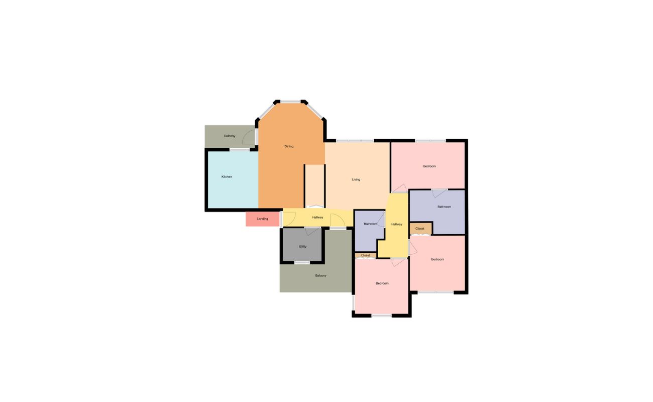
Home>diy>Architecture & Design>How To Read Floor Plan Symbols
Architecture & Design
How To Read Floor Plan Symbols
Modified: October 20, 2024
Learn how to interpret floor plan symbols in architecture and design. Enhance your understanding of blueprints and improve your ability to visualize spatial relationships.
(Many of the links in this article redirect to a specific reviewed product. Your purchase of these products through affiliate links helps to generate commission for Storables.com, at no extra cost. Learn more)
Introduction
Understanding floor plan symbols is crucial for anyone involved in architecture, interior design, or construction. Floor plan symbols are visual representations of various elements found in a building, such as walls, doors, furniture, and electrical appliances. These symbols provide a standardized way of communicating design concepts, making it easier for professionals to interpret and execute architectural plans.
In this article, we will delve into the world of floor plan symbols, exploring common symbols and their meanings. We will also discuss how to read and interpret floor plans effectively. Whether you are a homeowner looking to understand your home’s layout or a professional in the construction industry, this guide will help you navigate the intricate language of floor plan symbols.
Before we dive into the symbols themselves, it’s important to note that floor plan symbols can vary slightly depending on the region or industry. However, most symbols follow a similar pattern and carry universal meanings.
In the next sections, we will explore the most common symbols and their meanings, covering everything from walls and partitions to furniture and appliances, electrical and lighting symbols, plumbing symbols, and HVAC symbols. Additionally, we will touch on some additional symbols and notations that may be encountered in floor plans.
By the end of this article, you will have a solid understanding of floor plan symbols, allowing you to interpret architectural plans with confidence and precision. So let’s begin our journey into the world of floor plan symbols!
Key Takeaways:
- Understanding floor plan symbols is crucial for professionals in architecture, interior design, and construction. These symbols provide a standardized visual language for effective communication and accurate execution of design concepts.
- Familiarizing yourself with common floor plan symbols, such as walls, doors, furniture, and HVAC components, is essential for confidently interpreting architectural plans and visualizing the design and functionality of a space.
Read more: How To Read A Floor Plan Dimensions
Understanding Floor Plan Symbols
Before we can start deciphering floor plan symbols, it’s important to understand their purpose and how they are used. Floor plan symbols exist to provide a visual representation of different elements in a building, allowing architects, designers, and contractors to effectively communicate their ideas and plans.
When creating a floor plan, architects and designers use symbols to represent walls, doors, windows, furniture, appliances, and other important features. These symbols are drawn to scale and placed on the floor plan layout in relation to their real-world positioning.
By using symbols, professionals can convey important information about the layout, functionality, and design aspects of a building. This helps all stakeholders involved, including construction workers, contractors, and clients, to have a clear understanding of the intended design.
Reading floor plan symbols involves familiarizing yourself with the standard symbols used in the industry. Many symbols are intuitive and resemble the object or feature they represent. However, there are also symbols that may be more abstract or require additional knowledge to interpret accurately.
It’s worth noting that different industries may have variations in the symbols they use. For example, electrical symbols used in residential floor plans may differ slightly from those used in commercial or industrial plans. Therefore, it’s essential to refer to the specific guidelines and conventions of the industry you are working in.
Once you have a basic understanding of floor plan symbols, you can begin interpreting the various elements of a floor plan and gaining insights into the overall design. Being able to read floor plan symbols is an invaluable skill for anyone in the architecture, interior design, or construction field.
In the next sections, we will explore the most common floor plan symbols and their meanings, allowing you to build a solid foundation of knowledge for reading and understanding floor plans.
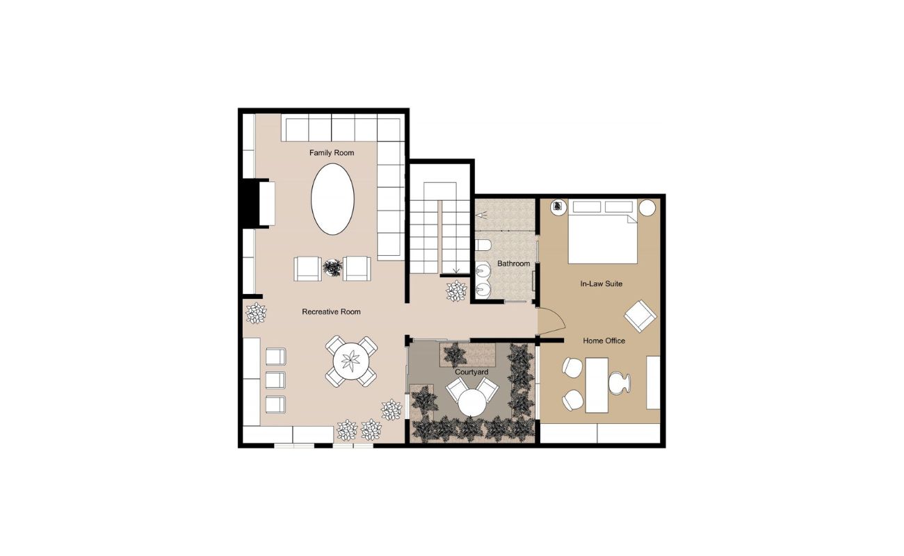
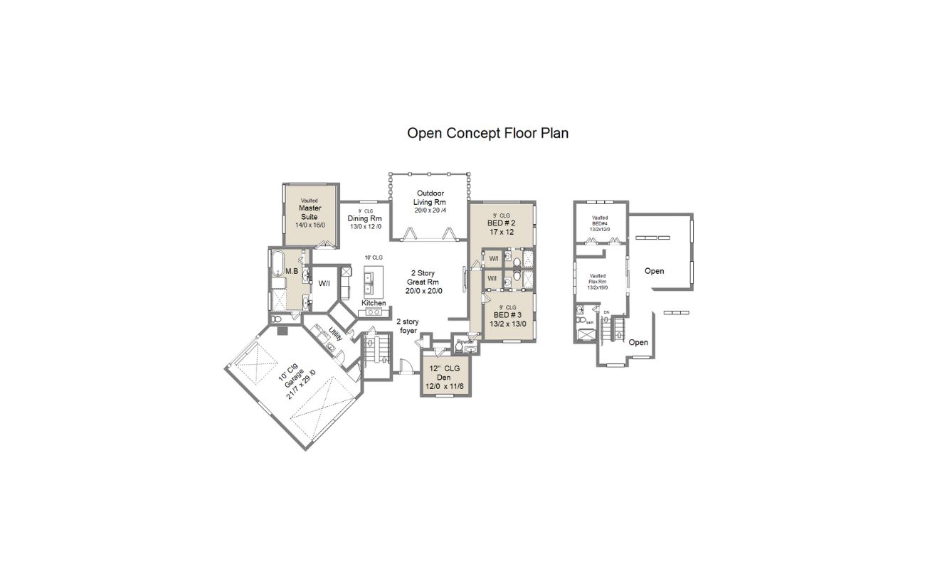
Common Symbols and Their Meanings
When it comes to floor plan symbols, there are several commonly used symbols that appear frequently in architectural and design plans. Let’s take a closer look at these symbols and their meanings:
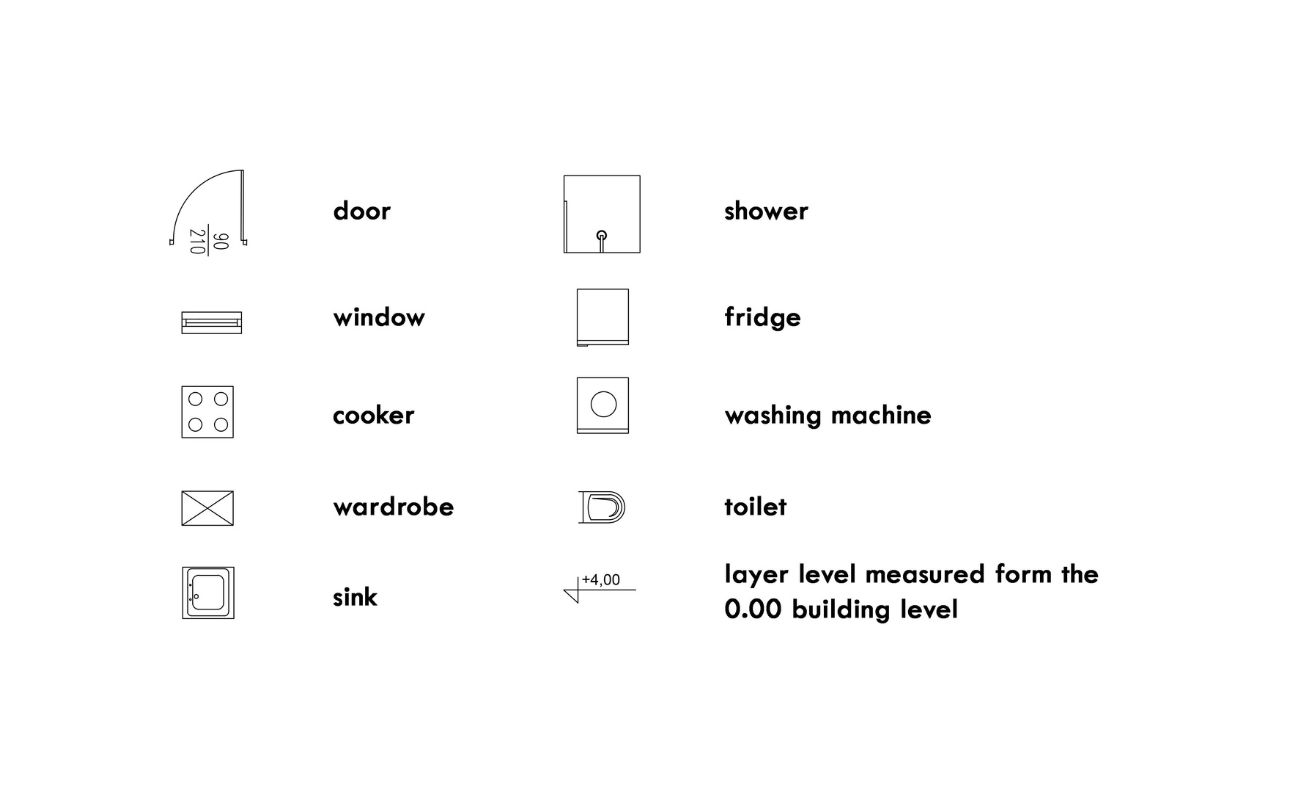
- Walls and Partitions: Walls and partitions are represented by solid lines in floor plans. They indicate the boundaries between different rooms or spaces. Interior walls are typically shown with solid lines, while exterior walls may be represented with thicker lines or additional symbols to indicate insulation or other construction details.
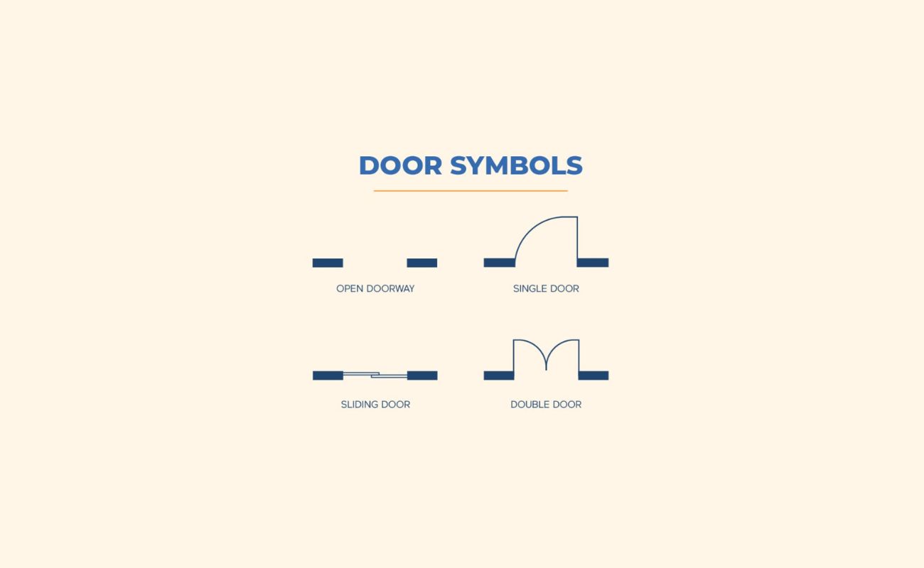
- Doors: Doors are symbolized with a line that has a small arc at one end. The arc represents the swinging direction of the door. A small line extending from the arc indicates the side on which the door hinges are located. Double doors are represented by two parallel lines with arcs at each end.
- Windows: Windows are typically represented by a solid line with diagonal lines crossing it. The diagonal lines indicate the direction in which the window opens, such as up or down for vertical windows and left or right for horizontal windows.
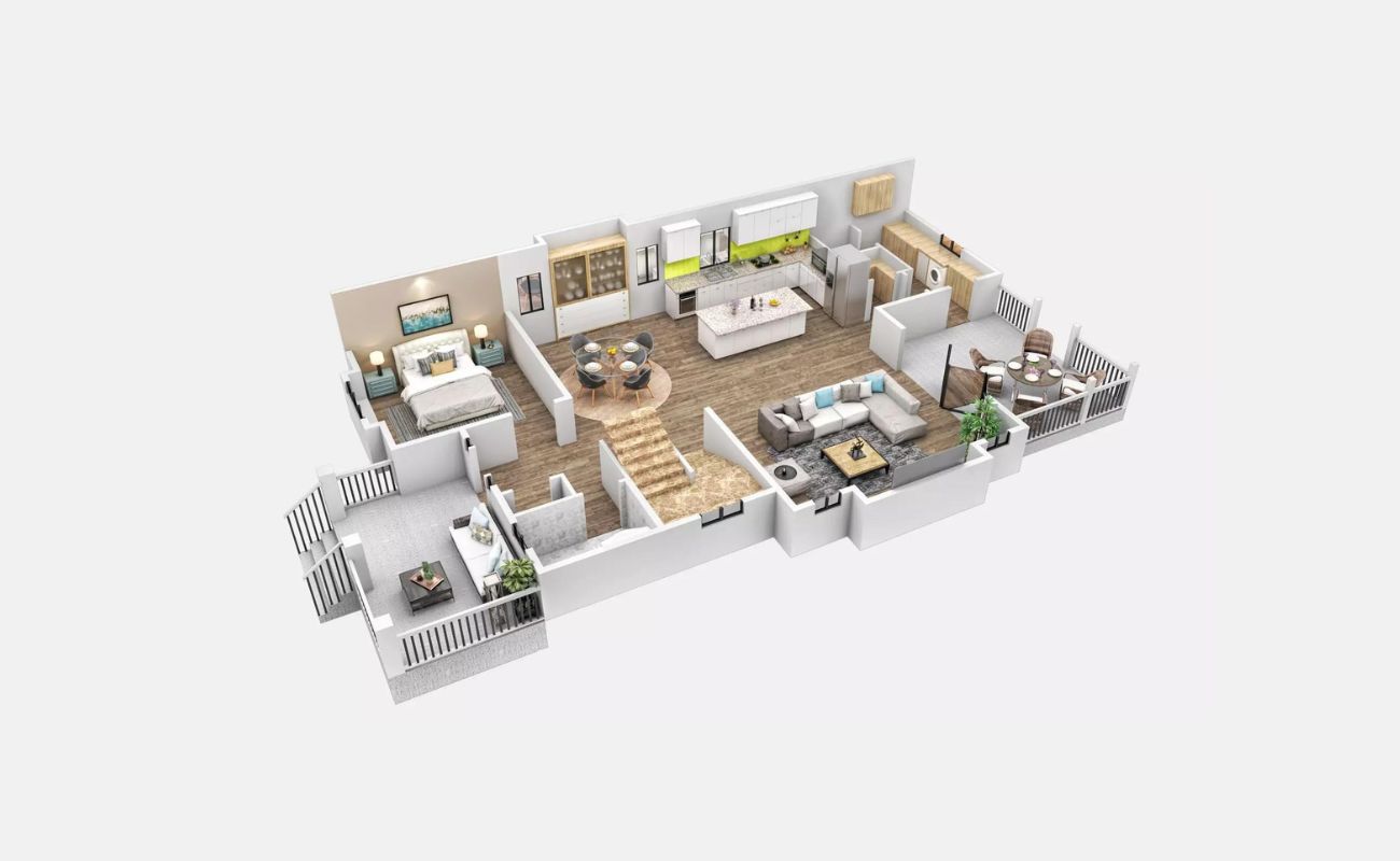
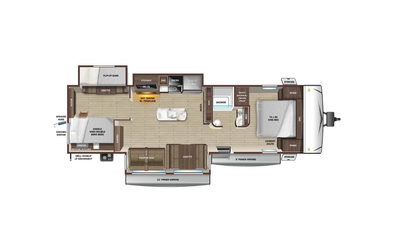
- Furniture and Appliances: Various furniture and appliances are represented by specific symbols in a floor plan. For example, beds are typically denoted by a rectangle with a shorter parallel line at the foot. Sofas and chairs are represented by simple rectangular shapes. Kitchen appliances, such as stoves and refrigerators, have their own set of symbols, often resembling the actual object in shape.
- Electrical and Lighting Symbols: Electrical symbols represent the location of electrical outlets, switches, and lighting fixtures in a floor plan. Outlets are depicted as small circles with lines indicating the location of the electrical wiring. Switches are shown as open or closed circles, and lighting fixtures are represented by various symbols depending on the type of fixture (ceiling-mounted, wall-mounted, etc.).
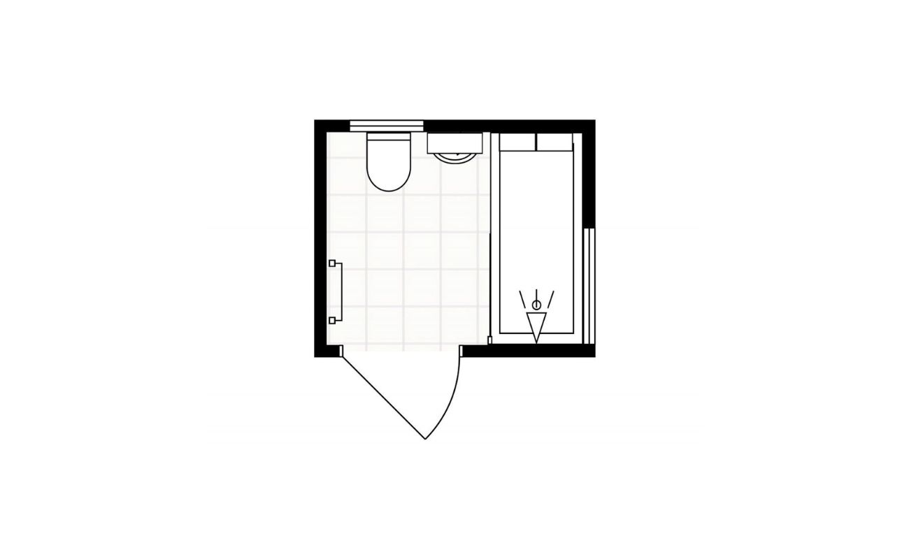
- Plumbing Symbols: Plumbing symbols indicate the location of plumbing fixtures, such as sinks, toilets, showers, and tubs. These symbols are typically simplified representations of the fixtures, often appearing as simple geometric shapes with labels to indicate their function.
- HVAC Symbols: HVAC (Heating, Ventilation, and Air Conditioning) symbols represent air vents, registers, ducts, and other components of a building’s HVAC system. These symbols are often straightforward and resemble the actual elements they represent, such as a simple rectangle for air registers or arrows indicating the direction of airflow.
These are just a few examples of the many symbols used in floor plans. It’s essential to familiarize yourself with the commonly used symbols in your specific field to effectively interpret and communicate design concepts.
In the next sections, we will explore more specific symbols related to walls, doors, windows, furniture, appliances, electrical and lighting, plumbing, HVAC, as well as additional symbols and notations that you may encounter in floor plans.
Walls and Partitions
Walls and partitions are crucial elements in floor plans as they define the layout and create separate spaces within a building. Understanding how walls and partitions are represented in floor plan symbols is essential for accurately interpreting architectural plans.
In most floor plans, walls are depicted as solid lines that outline the boundaries of rooms and provide structural support. These lines are typically drawn in varying thicknesses to indicate different types of walls, such as exterior walls, load-bearing walls, or non-load-bearing walls.
Load-bearing walls, which bear the weight of the structure above them, are usually depicted with thicker lines to differentiate them from non-load-bearing walls. Exterior walls may also include additional symbols or shading to represent insulation or other construction details.
Partitions, on the other hand, are used to divide open spaces or create separate rooms within a larger area. Partitions are typically represented by dashed lines, dotted lines, or thin solid lines. These lines do not carry the same structural weight as walls and can be easily reconfigured or removed.
In some cases, partitions may be represented by slightly thicker lines, especially if they have additional elements attached to them, such as built-in shelves or cabinets. These thicker lines help distinguish them from regular walls and provide more detail about their design and functionality.
When reading floor plan symbols related to walls and partitions, it’s important to pay attention to the thickness and style of the lines. This will help you differentiate between load-bearing walls, exterior walls, partitions, and other elements. Understanding the role and function of walls and partitions in a building will allow you to better interpret the spatial layout and overall design of a floor plan.
Now that we have covered walls and partitions, let’s move on to the symbols for doors and windows, which play a crucial role in the functionality and aesthetics of a building.
Doors and Windows
Doors and windows are essential components of any building, providing access, light, and ventilation. In floor plan symbols, doors and windows are represented using specific symbols that convey their location, size, and swing direction.
Doors are typically depicted as a line with an arc at one end. The line represents the door frame, while the arc indicates the swinging direction of the door. A small line extends from the arc to indicate the side on which the hinges are located. This helps to determine whether the door opens inwards or outwards. If the door swings in both directions, it will be represented with two arcs, one at each end of the line.
The size of the door is typically indicated by the length of the line representing the frame. Measurements may be included next to the symbol to specify the door width.
Windows, on the other hand, are represented by a solid line with diagonal lines crossing it. The diagonal lines indicate the direction in which the window opens. For vertical windows, the lines will be angled up or down to represent sliding or awning windows. For horizontal windows, the lines will be angled left or right to represent sliding or casement windows.
The size of the window may be indicated by the length of the solid line representing the window frame. Like with doors, measurements may be included to specify the window dimensions.
In addition to representing the swing direction or opening style, doors and windows may also include additional symbols to denote their type or special features. For example, a double door may be represented by two parallel lines with arcs at each end, indicating the two individual door leaves. Sliding doors may be indicated with double lines and an arrow symbol to show their sliding motion.
When interpreting floor plan symbols for doors and windows, it’s important to consider their placement and relationship to walls and partitions. This will help determine the flow of traffic and the overall functionality of the space.
Now that we have covered doors and windows, let’s move on to exploring the symbols used for furniture and appliances in floor plans.
Furniture and Appliances
Furniture and appliances are essential elements in floor plans as they determine the functionality and layout of a space. In floor plan symbols, furniture and appliances are represented using specific symbols that allow designers, architects, and contractors to envision how a space will be furnished and equipped.
When it comes to furniture, common symbols are used to represent various pieces such as beds, sofas, chairs, tables, and cabinets. Beds are typically represented by a rectangular shape with a shorter parallel line at the foot of the bed. Sofas and chairs are often depicted as simple rectangular shapes. Tables are represented by rectangular or circular shapes, depending on their design. Cabinets and storage units are usually shown as rectangular shapes with additional details to indicate doors, drawers, and shelves.
Appliances in a floor plan are represented by symbols that resemble the actual objects. For example, a stove may be depicted as a rectangle with smaller rectangles on top, representing the burners. A refrigerator may be shown as a rectangle with the shape of a double door. Other common appliances such as dishwashers, microwaves, and washing machines are also represented using specific symbols.
It’s important to note that the size and scale of furniture and appliances in floor plan symbols are not necessarily accurate representations of their actual dimensions. These symbols are meant to provide a general idea of their placement and arrangement within a space.
When reading floor plan symbols for furniture and appliances, it’s essential to consider their placement and relationship to walls, windows, and doors. This will help determine the flow of movement within a room and ensure that there is enough space for comfortable use of the furniture and appliances.
Understanding the symbols used for furniture and appliances in floor plans is crucial for visualizing the final design and ensuring that the space meets the functional needs of its occupants.
Now that we have covered furniture and appliances, let’s move on to exploring the symbols for electrical and lighting in floor plans.
When reading floor plan symbols, refer to the legend or key to understand the meaning of each symbol used in the plan. This will help you interpret the layout accurately.
Electrical and Lighting Symbols
In floor plans, electrical and lighting symbols are used to represent the location and type of electrical outlets, switches, and lighting fixtures. These symbols allow designers, architects, and electricians to accurately plan the electrical layout and ensure proper placement of outlets and fixtures.
Electrical outlets are commonly represented by small circles with lines indicating the location of the electrical wiring. The number of lines extending from the circle denotes the number of sockets in the outlet. Outlets may also be labeled with letters or symbols to indicate specific types, such as outlets with grounded connections or those designed for specialized equipment.
Switches, which control the flow of electricity to lights or other devices, are typically depicted as either open or closed circles. An open circle represents a switch in the off position, while a closed circle indicates that the switch is turned on. Switches may also be labeled with letters or symbols to indicate their function, such as “S” for a standard light switch or “T” for a three-way switch.
Lighting fixtures are represented by various symbols depending on their type and placement. Ceiling-mounted fixtures, such as chandeliers or recessed lights, are often indicated by a circle with lines emanating from it. Wall-mounted fixtures, such as sconces, are represented by a circle with lines extending vertically from it. Floor or table lamps may be depicted as a small circle with a line representing the lamp neck.
In addition to these basic symbols, specialty lighting fixtures, such as track lighting or pendant lights, may have their own unique symbols. These symbols are typically designed to resemble the physical appearance of the actual fixtures.
Understanding electrical and lighting symbols in floor plans is crucial for ensuring proper wiring and placement of outlets and fixtures. It allows for effective communication between architects, electricians, and other professionals involved in the construction process.
Now that we have covered electrical and lighting symbols, let’s move on to exploring the symbols used for plumbing in floor plans.
Plumbing Symbols
In floor plans, plumbing symbols are used to represent the location and type of plumbing fixtures, such as sinks, toilets, showers, and tubs. These symbols allow designers, architects, and plumbers to accurately plan the plumbing layout and ensure proper placement and connection of fixtures.
Plumbing symbols in floor plans are typically simplified representations of the actual fixtures. For example, a sink may be represented by a circle with a small perpendicular line indicating the position of the faucet. A toilet is often depicted as an oval shape with a smaller oval inside, representing the bowl and the tank. Showers and tubs may be represented by simple rectangular shapes.
To indicate the plumbing connections and pipes, symbols such as lines and arrows are used. Pipes are typically represented as straight lines connecting the plumbing fixtures. Arrows are used to indicate the flow of water or the direction of the plumbing pipes.
In addition to these basic symbols, special plumbing fixtures or features may have their own unique symbols. For example, symbols for bidets, urinals, or utility sinks may differ slightly from the symbols used for standard sinks and toilets.
It’s important to pay attention to the positioning and relationship of plumbing symbols in floor plans. This helps to determine the flow of water and ensure proper connections with water supply lines and drainage systems.
Understanding plumbing symbols in floor plans is essential for coordinating the installation of plumbing fixtures and ensuring that the plumbing system functions effectively and efficiently.
Now that we have covered plumbing symbols, let’s move on to exploring the symbols used for HVAC (Heating, Ventilation, and Air Conditioning) systems in floor plans.
HVAC Symbols
HVAC (Heating, Ventilation, and Air Conditioning) systems play a crucial role in maintaining comfort and air quality in buildings. In floor plans, HVAC symbols are used to represent various components of the HVAC system, such as air vents, registers, ducts, and equipment. These symbols help designers, architects, and contractors plan and coordinate the installation of the HVAC system.
Air vents and registers are typically represented by simple rectangular shapes with slits or grids to indicate the location of air flow. Vents may also have labels to specify whether they are supply vents or return vents. The symbols for vents and registers can vary in design depending on the specific style or type of ventilation system being used.
HVAC equipment, such as furnaces, air conditioners, and heat pumps, may be represented by symbols that resemble their physical appearance. For example, a furnace may be shown as a rectangular shape with additional details indicating the venting and fuel source. Air conditioners are often depicted as a square or rectangular shape with wavy lines to indicate cool air flow.
Ductwork, which carries air throughout the building, is represented by straight lines or curves with arrows to indicate the direction of airflow. These lines connect the HVAC equipment to the vents and registers, illustrating the path of conditioned air.
It’s important to understand the symbols used for HVAC systems in floor plans to ensure proper placement and coordination of the different components. This allows for efficient air circulation, temperature control, and ventilation in the building.
Now that we have covered HVAC symbols, let’s move on to exploring additional symbols and notations that may be encountered in floor plans.
Read more: How To Read Construction Site Plans
Additional Symbols and Notations
In addition to the common symbols we have discussed so far, there are several other symbols and notations that may be encountered in floor plans. These symbols provide additional information about the design, construction, or specific features of a building. Let’s explore some of these additional symbols and notations:
- Dimensions: Floor plans often include measurements and dimensions to indicate the size and scale of rooms, walls, and other elements. These measurements are usually represented by lines with numbers indicating the length or width of the corresponding element.
- Material or finish notations: Symbols or abbreviations may be used to indicate the type of materials or finishes applied to certain surfaces, such as flooring or wall treatments. These notations help convey design and construction details to ensure proper execution.
- Stairs and elevators: Symbols for stairs and elevators are used to represent the vertical circulation within a building. Stairs may be depicted with lines indicating each step, and elevators are usually represented by a simple rectangle with doors.
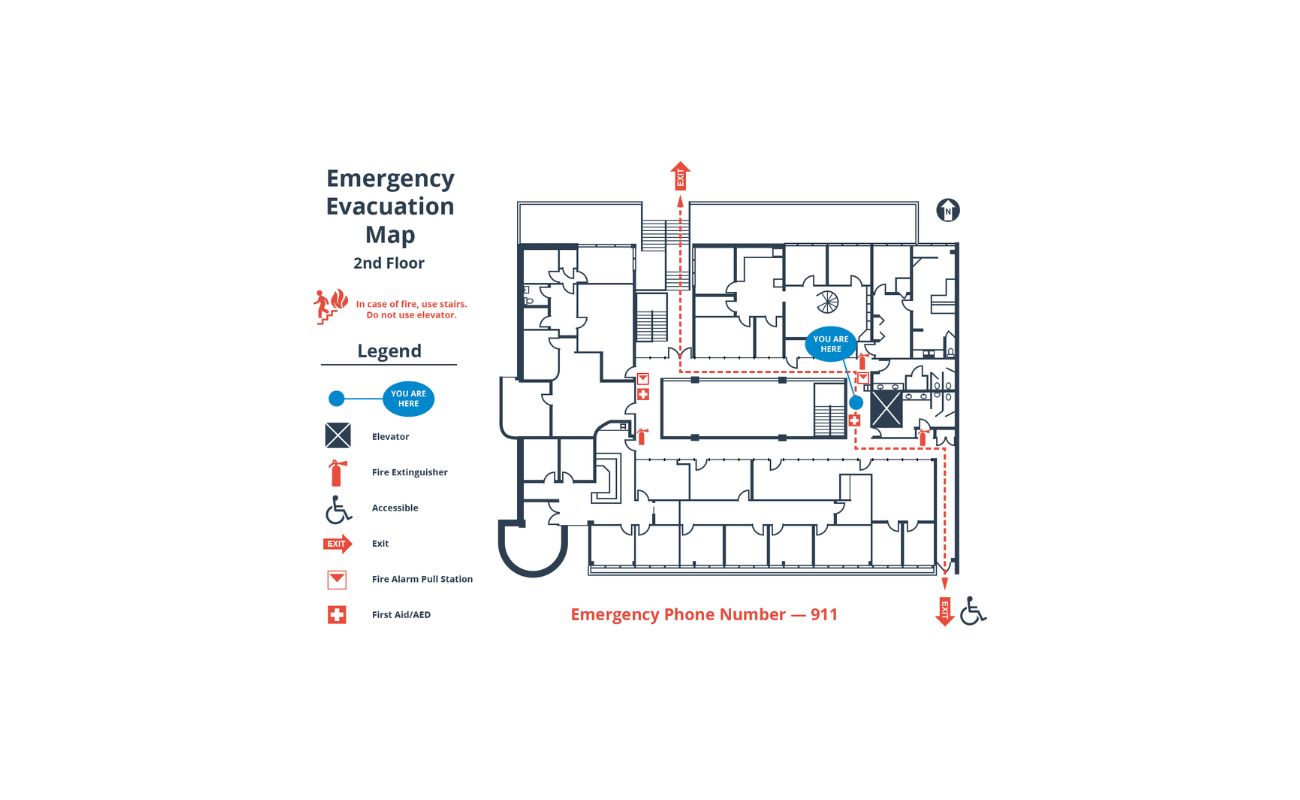
- Fire safety: Floor plans may include symbols and notations related to fire safety features, such as fire extinguishers, exit signs, emergency lighting, or fire alarm systems. These symbols are crucial for ensuring compliance with building codes and ensuring the safety of occupants.
- Arcs and circles: Arcs and circles are commonly used in floor plans to represent curved walls, rounded corners, or specific design elements. These shapes add visual interest and can indicate architectural details.
- Notations for special features: Symbols or text notations may be used to denote special features or custom elements in a building, such as built-in shelving, fireplaces, or decorative details. These notations provide additional information to guide the construction process.
It’s important to familiarize yourself with these additional symbols and notations as they contribute to a more comprehensive understanding of the floor plan and the intended design of the building. Paying attention to these details ensures accurate interpretation and execution of the architectural plans.
Now that we have covered both the common symbols and additional symbols in floor plans, let’s conclude our exploration of floor plan symbols.
Conclusion
Understanding floor plan symbols is essential for anyone involved in architecture, interior design, or construction. These symbols provide a visual language that allows professionals to communicate design concepts, plan layouts, and ensure accurate execution of architectural plans.
In this article, we have explored the world of floor plan symbols, covering common symbols and their meanings. We discussed walls and partitions, doors and windows, furniture and appliances, electrical and lighting symbols, plumbing symbols, HVAC symbols, as well as additional symbols and notations that may be encountered in floor plans.
By familiarizing yourself with these symbols, you can confidently interpret and navigate the intricate language of floor plans. Whether you are a professional in the field or a homeowner looking to understand your home’s layout, this knowledge will help you effectively communicate your ideas and better visualize the design and functionality of a space.
Remember, floor plan symbols may vary slightly depending on the region or industry, so it’s important to refer to the specific guidelines and conventions of your field. By staying up-to-date with the latest standards and practices, you can ensure accurate interpretation and seamless collaboration with other professionals.
So whether you’re reading floor plans for a new construction project or trying to understand the layout of your own home, keep in mind that floor plan symbols are the key to unlocking the design details and envisioning the final result.
Now, armed with this knowledge, you can confidently navigate the world of floor plan symbols and bring your architectural visions to life.
Frequently Asked Questions about How To Read Floor Plan Symbols
Was this page helpful?
At Storables.com, we guarantee accurate and reliable information. Our content, validated by Expert Board Contributors, is crafted following stringent Editorial Policies. We're committed to providing you with well-researched, expert-backed insights for all your informational needs.

0 thoughts on “How To Read Floor Plan Symbols”