Home>diy>Architecture & Design>How To Measure Angle In CAD
Architecture & Design
How To Measure Angle In CAD
Modified: October 18, 2024
Learn how to accurately measure angles in CAD for architecture and design projects. Master the essential techniques to enhance precision and efficiency.
(Many of the links in this article redirect to a specific reviewed product. Your purchase of these products through affiliate links helps to generate commission for Storables.com, at no extra cost. Learn more)
Introduction
When it comes to designing and drafting in the world of architecture and engineering, accuracy is paramount. Every detail, every measurement, and every angle must be precisely calculated and accounted for. This is where CAD (Computer-Aided Design) software comes into play. CAD software not only allows designers to create complex 2D and 3D models, but it also provides advanced measurement tools to ensure accuracy in the design process.
One crucial aspect of design that often requires accurate measurement is the determination of angles. Angles play a vital role in determining the orientation, placement, and alignment of various components of a design. Whether it’s the slope of a roof, the rotation of a mechanical part, or the inclination of a ramp, measuring angles correctly is essential for the overall success of a project.
In this article, we will explore the various methods for measuring angles in CAD software. We will delve into the tools available within CAD software that make angle measurement a breeze. Additionally, we will share best practices for ensuring accurate angle measurement in CAD, allowing you to confidently execute your designs with precision.
Key Takeaways:
- Embrace the power of CAD software’s advanced measurement tools to accurately measure angles, ensuring precision and efficiency in architectural and engineering designs.
- Familiarize yourself with CAD software’s protractor, smart dimension, and angle measurement tools to confidently and accurately measure angles, enhancing the quality and success of your design projects.
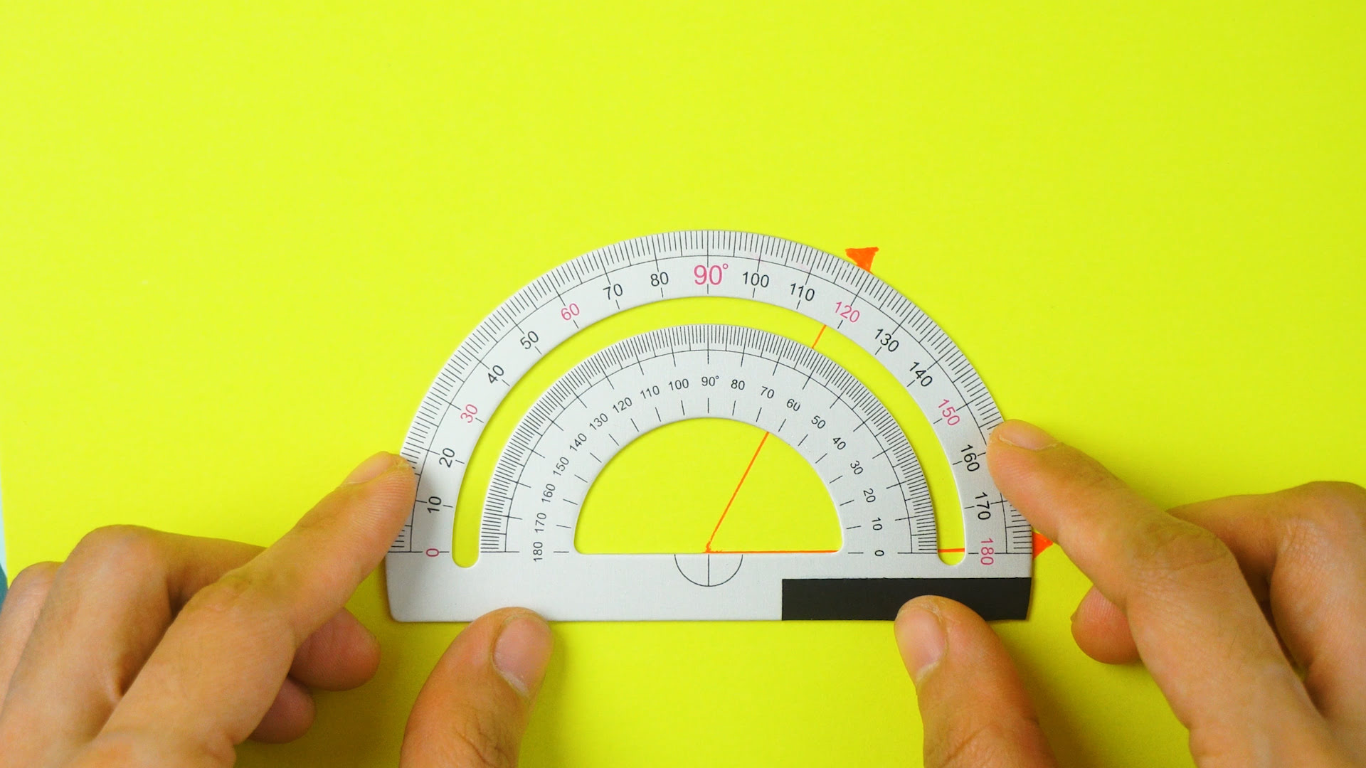
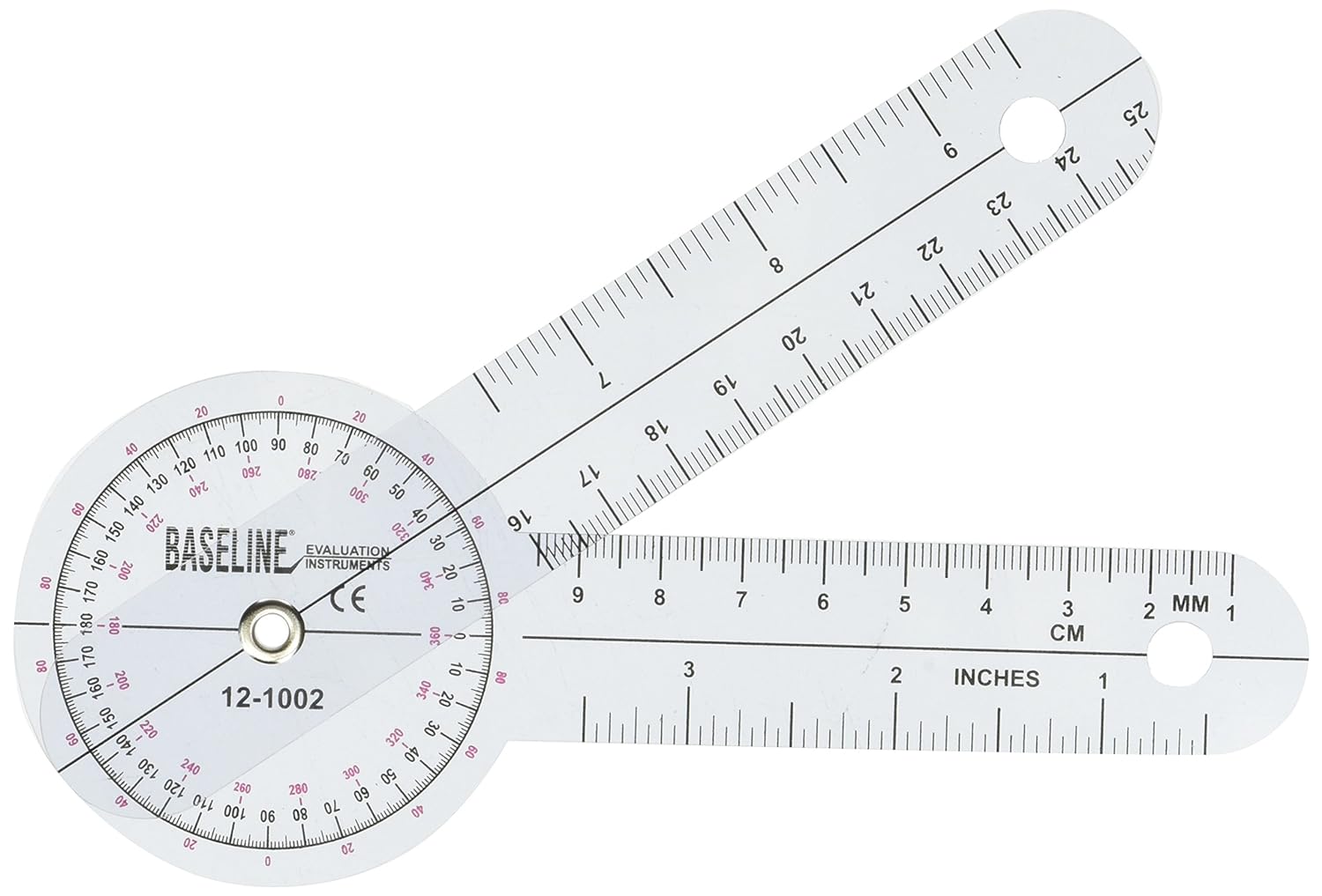
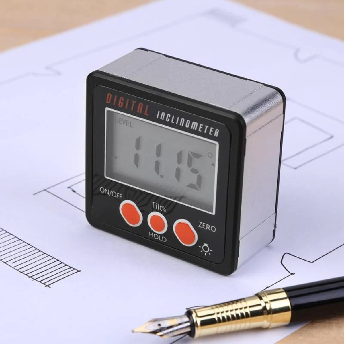
Read more: How To Use Digital Protractor
Understanding Angle Measurement in CAD
Before we dive into the methods for measuring angles in CAD software, it’s important to understand how angle measurement works within the digital realm. In CAD, angles are typically measured in degrees, just like in everyday mathematics. A degree is a unit of measurement used to quantify the size of an angle, with a full circle being 360 degrees.
When working with angles in CAD, it’s crucial to grasp the concept of a reference line or axis. The reference line serves as the baseline against which other lines or objects are measured. It provides a standard starting point for angle measurement. CAD software typically allows you to select these reference lines before measuring an angle, providing flexibility and precision in your calculations.
In addition to degrees, CAD software often offers the option to measure angles in radians or gradients. Radians are another way of measuring angles, commonly used in trigonometry. Gradients, on the other hand, are a measurement system based on a 400-degree circle. While degrees are the most commonly used unit for angle measurement in CAD, it’s worth noting that different industries and applications may require alternative units, and CAD software usually accommodates those needs.
Understanding how CAD software handles angle measurement is crucial for accurately translating your design intent onto the digital canvas. With this knowledge in mind, let’s move on to the various methods available for measuring angles in CAD software.
Methods for Measuring Angles in CAD Software
CAD software offers a variety of methods for measuring angles, each with its own specific tools and functionality. Let’s take a look at three common methods you can use to measure angles in CAD.
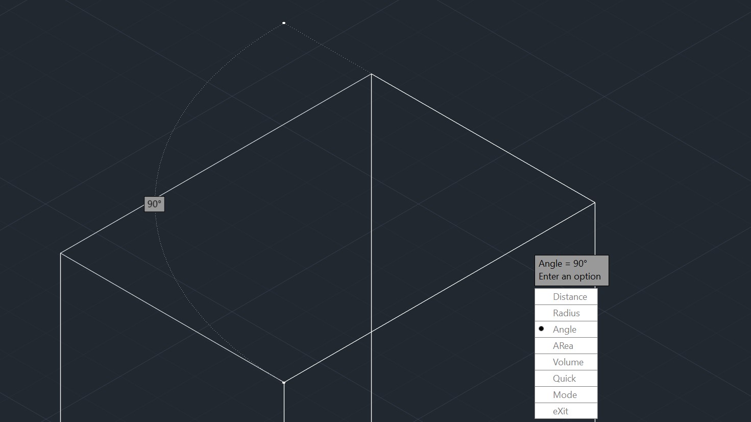
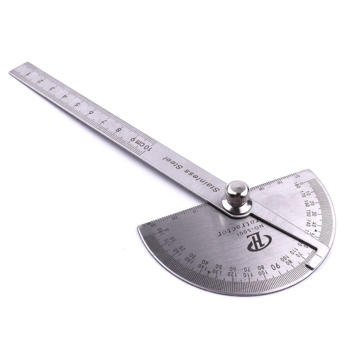
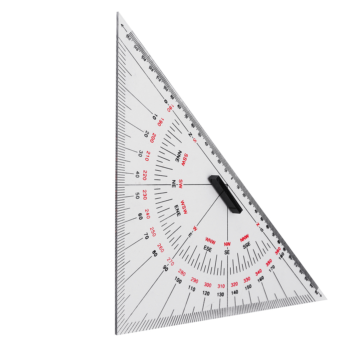
1. Protractor Tool: The protractor tool is a fundamental feature in CAD software that allows you to measure angles with precision. Similar to a physical protractor, this tool is used to measure angles by aligning its base with the reference line and reading the angle displayed on the protractor’s scale. CAD software provides an on-screen representation of a protractor, making it easy to accurately measure angles in your design.
2. Smart Dimension Tool: The smart dimension tool is another valuable tool in CAD software that enables you to measure and display precise dimensions, including angles. By selecting two points on an angle and using the smart dimension tool, you can automatically calculate and display the exact angle value. This method is especially useful when you need to measure specific angles within your design.
3. Angle Measurement Tool: Some CAD software offers a dedicated angle measurement tool that allows you to measure angles more efficiently. With this tool, you can simply select the lines or objects that form the angle, and the software will automatically calculate and display the angle value. The angle measurement tool streamlines the process, eliminating the need for manual calculations or additional steps.
These methods provide you with the necessary tools to measure angles accurately in your CAD designs. It’s essential to familiarize yourself with these tools and explore the specific functionalities of your chosen CAD software to ensure optimal angle measurement capabilities.
Now that we have covered the basic methods for measuring angles in CAD software, let’s explore how to use these tools effectively in practice.
Using the Protractor Tool
The protractor tool is a valuable feature in CAD software that allows you to measure angles with precision. It replicates the functionality of a physical protractor, making it easy to measure angles in your design accurately. Here’s how you can use the protractor tool in CAD software:
1. Select the Protractor Tool: Open your CAD software and locate the protractor tool. It is usually found in the toolbar or the measurement tools menu. Click on the protractor tool to activate it.
2. Align the Base: Determine the reference line or axis against which you want to measure the angle. Align the base of the protractor tool with this line. You can do this by clicking on the starting point of the reference line and dragging the protractor tool along the line until its base aligns with it.
3. Read the Angle: Once the protractor tool is aligned with the reference line, you will see the degree scale of the protractor displayed on the screen. Look for the indicator or marker on the scale that intersects with the other line or object forming the angle. The value at this point represents the angle measurement in degrees.
4. Record or Apply the Angle: After determining the angle measurement, you can choose to record the value for future reference or apply it to your design. Depending on the CAD software you are using, you may have the option to input the measured angle directly into the software or use it for positioning or aligning other elements in your design.
Using the protractor tool allows you to measure angles accurately within your CAD design. It provides a visual representation of the angle and eliminates the need for manual calculations. However, it’s important to note that different CAD software may have slight variations in how the protractor tool is accessed or used. Consulting the user manual or online resources specific to your software can offer further guidance on utilizing this tool effectively.
In the next section, we will explore another method for measuring angles in CAD software – the smart dimension tool.
When measuring angles in CAD, use the “angle” command to accurately measure the angle between two lines or objects. This will provide you with the precise measurement you need for your design.
Using the Smart Dimension Tool
The smart dimension tool is a powerful feature in CAD software that allows you to measure and display precise dimensions, including angles, within your design. This tool eliminates the need for manual calculations and provides accurate angle measurements. Here’s how you can use the smart dimension tool in CAD software:
1. Select the Smart Dimension Tool: Open your CAD software and locate the smart dimension tool. It is typically found in the toolbar or the dimensioning tools menu. Click on the smart dimension tool to activate it.
2. Select the Angle: Identify the lines or objects that form the angle you want to measure. Click on the first line, then click on the second line to define the angle measurement.
3. Read the Angle: Once you have selected the lines or objects, the smart dimension tool will automatically calculate and display the angle measurement. The angle value will be shown near the angle itself or in a separate dimension text box.
4. Adjust the Dimension Display: Depending on your CAD software, you may have the option to customize the display of the angle dimension. You can change the text size, position, or format to suit your preferences or match the project requirements.
5. Apply the Angle Value: After measuring the angle, you can choose to apply the measured value to your design. This can be used for positioning other elements, determining the orientation of components, or ensuring proper alignment within your CAD model.
The smart dimension tool simplifies the process of measuring angles in CAD software. It eliminates the need for manual calculations and allows for precise dimensioning. However, it’s important to note that the availability and specific functionality of the smart dimension tool may vary depending on the CAD software you are using. Refer to the user manual or online resources for your specific software to explore the full range of features and capabilities.
In the next section, we will discuss another method for measuring angles in CAD – the angle measurement tool.
Using the Angle Measurement Tool
The angle measurement tool is a handy feature available in some CAD software that simplifies the process of measuring angles within your design. This dedicated tool allows you to quickly and accurately measure angles without the need for manual calculations. Here’s how you can use the angle measurement tool in CAD software:
1. Select the Angle Measurement Tool: Open your CAD software and locate the angle measurement tool. It is typically located in the toolbar or the measurement tools menu. Click on the angle measurement tool to activate it.
2. Select the Lines or Objects: Identify the lines or objects that form the angle you want to measure. Use the cursor or selection tool to click on each line or object.
3. Read the Angle Measurement: Once you have selected the lines or objects, the angle measurement tool will automatically calculate and display the angle value. The measurement will be shown either near the angle itself or in a separate text box.
4. Adjust the Display Settings: Depending on your CAD software, you may have the option to customize the display of the angle measurement. You can modify the text size, format, or position of the angle dimension to suit your needs or project requirements.
5. Apply the Angle Measurement: After obtaining the angle measurement, you can utilize it in various ways within your design. This might involve positioning other elements, determining the orientation of components, or ensuring proper alignment throughout your CAD model.
The angle measurement tool simplifies the process of measuring angles in CAD software. It streamlines the calculation process and provides precise angle measurements with ease. However, it’s important to note that the availability and specific functionality of the angle measurement tool may vary depending on the CAD software you are using. Consult the user manual or online resources for your specific software to explore the full range of features and capabilities.
In the next section, we will discuss best practices for ensuring accurate angle measurement in CAD.
Best Practices for Accurate Angle Measurement in CAD
Accurate angle measurement is essential when working with CAD software to ensure precise and reliable designs. Here are some best practices to follow for measuring angles accurately in CAD:
1. Select Clear Reference Lines: When measuring angles, it’s crucial to identify and define clear reference lines or axes. These lines serve as the baseline against which the angle will be measured. Ensure that the reference lines are distinct and easily distinguishable from other lines or objects in your design.
2. Zoom In for Precise Selection: To improve accuracy, zoom in on the area where the angle is located. This allows you to select the lines or objects forming the angle more precisely, minimizing the chance of errors or selecting unintended elements.
3. Use Snapping or Object Tracking: Utilize the snapping or object tracking features in your CAD software to ensure accurate selection of lines or objects. These tools help you align the references points precisely, making it easier to measure angles with precision.
4. Double-Check Measurement Tools: Always double-check the measurement tools you are using to measure angles. Confirm that the protractor tool, smart dimension tool, or angle measurement tool is correctly calibrated and providing accurate results. Use known angles or reference measurements to verify the accuracy of the tools if necessary.
5. Ensure Proper Units: Confirm that the CAD software is set to the correct unit of measurement for angles. Whether you prefer degrees, radians, or gradients, ensure that the software is configured to display and measure angles in your desired unit.
6. Periodically Update Software: Keep your CAD software up to date with the latest updates and patches. Software updates often include bug fixes and improvements to measurement tools, ensuring more accurate angle measurements and overall performance.
7. Practice Consistency: Maintain consistency in the use of measurement methods and tools throughout your design. Using different tools or techniques for measuring angles within the same project can introduce discrepancies and compromise the accuracy of your design.
8. Double-Check Critical Angles: Pay extra attention to angles that are critical to the functionality or aesthetics of your design. Double-check these angles using multiple measurement methods or tools to ensure accuracy and avoid potential issues during the construction or manufacturing phase.
By following these best practices, you can ensure accurate angle measurement in your CAD designs. Remember, precision in angle measurement directly contributes to the overall accuracy and quality of your designs, allowing for smooth execution and successful project outcomes.
Now, let’s conclude our exploration of measuring angles in CAD software.
Conclusion
Measuring angles accurately is a fundamental aspect of CAD design. With the availability of advanced measurement tools, CAD software has made angle measurement more precise and efficient than ever before. Whether you use the protractor tool, smart dimension tool, or angle measurement tool, each method offers its own advantages for determining angles within your design.
Understanding angle measurement in CAD software is essential. Familiarize yourself with the concept of reference lines or axes and the various units of measurement, such as degrees, radians, and gradients. These foundational principles will help you approach angle measurement with confidence and accuracy.
When using the protractor tool, align the base with the reference line and read the angle displayed on the scale. The smart dimension tool allows for automatic angle calculation based on selected lines or objects, and the angle measurement tool simplifies the process further by directly measuring the angle between selected elements.
To ensure accurate angle measurement in CAD, implement best practices such as selecting clear reference lines, zooming in for precise selection, and using snapping or object tracking tools. Double-check the measurement tools, verify the units of measurement, and keep your CAD software up to date.
By following these best practices and utilizing the available measurement tools effectively, you can confidently measure angles in CAD software and create designs that meet the desired specifications and requirements.
Remember, accuracy in angle measurement plays a vital role in the success of your architectural or engineering projects. With proper techniques and careful attention to detail, you can achieve the level of precision needed to bring your design concepts to life.
So, embrace the power of CAD software, leverage its angle measurement tools, and unlock new possibilities in your design journey. Measure angles with confidence, and let your creativity soar in the world of architecture and engineering.
Frequently Asked Questions about How To Measure Angle In CAD
Was this page helpful?
At Storables.com, we guarantee accurate and reliable information. Our content, validated by Expert Board Contributors, is crafted following stringent Editorial Policies. We're committed to providing you with well-researched, expert-backed insights for all your informational needs.


0 thoughts on “How To Measure Angle In CAD”