Home>Home Security and Surveillance>How To Build A Motion Detector Circuit
Home Security and Surveillance
How To Build A Motion Detector Circuit
Modified: March 6, 2024
Learn how to build a motion detector circuit for home security and surveillance. Step-by-step guide with easy-to-follow instructions.
(Many of the links in this article redirect to a specific reviewed product. Your purchase of these products through affiliate links helps to generate commission for Storables.com, at no extra cost. Learn more)
Introduction
Home security is a top priority for many homeowners. With the increasing concerns about burglaries and break-ins, it is essential to ensure the safety of your property and loved ones. A reliable home security and surveillance system can provide the peace of mind you need, knowing that your home is protected at all times.
One crucial component of a comprehensive home security system is a motion detector circuit. A motion detector circuit is designed to detect any movement within its range and trigger an alert or activate other security measures. It is an integral part of home security systems, providing an added layer of protection against potentially unauthorized access.
In this article, we will walk you through the process of building a motion detector circuit for your home. We will discuss the required components, circuit diagram, working principle, design and construction, testing and calibration, as well as troubleshooting tips. So, let’s dive in and learn how to create a motion detector circuit that will enhance the security of your home.
Key Takeaways:
- Building a motion detector circuit for home security involves components like PIR sensor, microcontroller, and relay module. It detects motion, triggers alarms, and enhances protection for your home and loved ones.
- Testing and troubleshooting are crucial for ensuring the reliability of a motion detector circuit. It’s important to verify power supply, adjust sensor settings, and address common issues for optimal performance.
Read more: How To Build A Motion Detector Alarm System
Components Required
Before you start building your motion detector circuit, it’s important to gather all the necessary components. Here are the key components you will need:
- PIR Sensor: The PIR (Passive Infrared) sensor is the heart of the motion detector circuit. It detects infrared radiation emitted by objects in its field of view.
- Microcontroller or Arduino board: The microcontroller or Arduino board is responsible for processing the signals from the PIR sensor and triggering the desired actions.
- Relay module: The relay module is used to control other devices or systems based on the signals received from the PIR sensor.
- LEDs: LEDs (Light Emitting Diodes) are used to indicate the status of the motion detector circuit, such as detecting motion or system armed.
- Resistors and Capacitors: These electronic components are required for proper signal conditioning and voltage regulation.
- Jumper wires: Jumper wires are used to establish connections between different components on the circuit board.
- Breadboard or PCB (Printed Circuit Board): You can choose to use a breadboard for prototyping or create a custom PCB for a more permanent circuit.
- Power supply: A suitable power supply is needed to provide the required voltage to the circuit components.
It’s important to ensure the quality and compatibility of the components you choose. Look for reliable suppliers and verified products to guarantee the effectiveness and longevity of your motion detector circuit.
Circuit Diagram
Now that you have gathered all the necessary components, let’s move on to the circuit diagram. The circuit diagram will guide you in connecting the various components together to create the motion detector circuit.
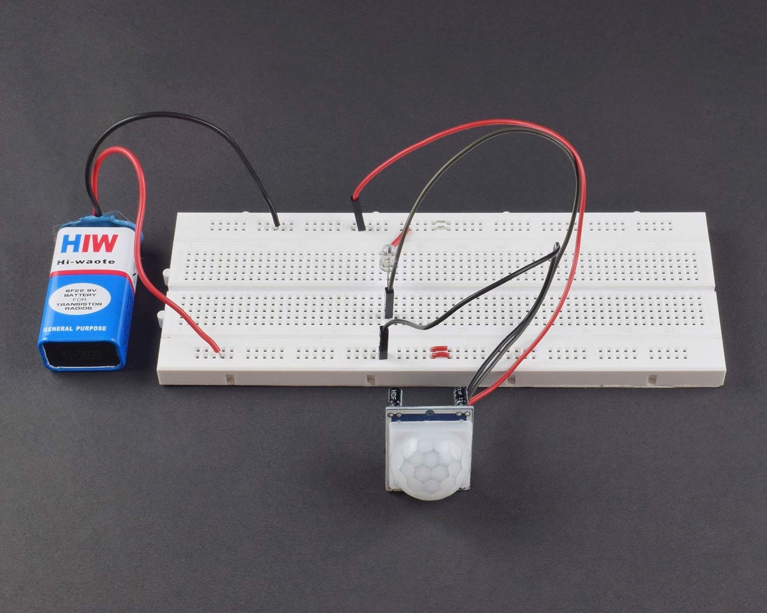
Here is a basic circuit diagram for a motion detector circuit:

In this circuit diagram, the PIR sensor is connected to the microcontroller or Arduino board. The output pin of the PIR sensor is connected to one of the digital input pins of the microcontroller. The microcontroller processes the signal from the PIR sensor and controls the relay module accordingly.
The relay module is connected to other devices or systems, such as an alarm system, lights, or cameras, depending on your specific requirements. The LEDs are also connected to the microcontroller to indicate the status of the motion detector circuit.
It’s important to follow the specific pin configurations and connections based on the datasheets of the components you are using. Double-check your connections to ensure accuracy and minimize any potential errors.
Now that you have a clear understanding of the circuit diagram, let’s move on to the next section to learn about the working principle of the motion detector circuit.
Working Principle
The working principle of a motion detector circuit relies on the detection of changes in infrared radiation within its range. The PIR sensor is the key component responsible for sensing these changes.
Passive Infrared (PIR) sensors are designed to detect the heat energy emitted by objects in their field of view. When an object moves within the range of the sensor, it emits infrared radiation that is captured by the sensor’s lens. This change in infrared radiation triggers the sensor to generate an electrical signal.
The electrical signal from the PIR sensor is then sent to the microcontroller or Arduino board. The microcontroller processes the signal and determines if motion has been detected. If motion is detected, it can take various actions, such as activating an alarm, turning on lights, or recording video footage.
Typically, the microcontroller controls a relay module, which acts as a switch to control other devices or systems. For example, when motion is detected, the microcontroller can signal the relay module to activate an alarm or turn on lights. This immediate response can help deter potential intruders.
The LEDs connected to the microcontroller serve as visual indicators, providing feedback on the status of the motion detector circuit. For instance, an LED may light up to indicate that the circuit is armed and ready to detect motion.
The working principle of a motion detector circuit can be summed up as follows: the PIR sensor detects changes in infrared radiation, sends a signal to the microcontroller, which then triggers appropriate actions through the relay module and provides visual feedback through the connected LEDs.
Understanding the working principle of the motion detector circuit is crucial for its design and calibration. In the next section, we will delve into the design and construction process to help you build a reliable and effective motion detector circuit.
When building a motion detector circuit, make sure to use a passive infrared sensor (PIR) to detect changes in infrared radiation caused by movement. This will ensure accurate detection of motion.
Design and Construction
Designing and constructing a motion detector circuit requires careful consideration of various factors such as range, sensitivity, and placement of components. Here are the key steps to follow:
- Determine the Range: Determine the desired range of detection for your motion detector circuit. This will depend on the size of the area you want to monitor. PIR sensors typically have a detection range of a few meters to tens of meters.
- Select the PIR Sensor: Choose a PIR sensor that matches your desired range and sensitivity requirements. Consider factors such as the field of view, detection angle, and adjustable sensitivity options.
- Choose the Microcontroller: Select a microcontroller or Arduino board that can handle the processing requirements of your motion detector circuit. Consider factors such as the number of digital input pins and compatibility with the chosen PIR sensor.
- Connect the Components: Follow the circuit diagram and connect the PIR sensor, microcontroller, relay module, LEDs, resistors, capacitors, and other components as per the specified connections. If using a breadboard, ensure the connections are secure. Alternatively, design and fabricate a custom printed circuit board (PCB) for a more permanent solution.
- Code the Microcontroller: Write the code for the microcontroller to process the signals from the PIR sensor and control the relay module. The code should include logic for detecting motion, triggering actions, and managing the LEDs for visual feedback.
- Assemble and Test: Assemble the circuit components into an enclosure to protect them from environmental factors. Test the motion detector circuit by moving within its range and observing the intended actions, such as triggering an alarm or activating lights.
During the design and construction process, it’s important to refer to the datasheets and documentation of the chosen components for specific instructions and guidelines. Ensure proper grounding and insulation of the circuit to avoid any electrical hazards.
Remember to keep the design modular and expandable, allowing for future upgrades or additions to your home security system. Once you have completed the design and construction of your motion detector circuit, it’s time to proceed to the testing and calibration phase.
Read more: How To Deactivate A Motion Detector
Testing and Calibration
Testing and calibration are crucial steps in ensuring the reliability and accuracy of your motion detector circuit. Here are some steps to follow for effective testing and calibration:
- Verify Power Supply: Ensure that the power supply is providing the correct voltage to the circuit components. Use a multimeter to measure the voltage and confirm its stability.
- Check Sensor Alignment: Make sure the PIR sensor is correctly aligned and positioned to cover the desired area. Adjust the detection angle and sensitivity, if possible, for optimal performance.
- Test Range: Test the range of the motion detector circuit by moving within its detection area. Verify that it accurately detects motion and triggers the desired actions.
- Adjust Sensitivity: Fine-tune the sensitivity of the PIR sensor to minimize false positives or missed detections. This can be done by adjusting the sensitivity settings, if available, or adding additional components, such as capacitors, for signal conditioning.
- Calibrate Delay: Set the appropriate delay time for the circuit’s response to motion detection. This determines the duration for which the circuit remains active after detecting motion. Adjust the delay according to your specific requirements or security protocols.
- Test Alarm and Actions: Verify that the motion detector circuit is triggering the intended actions, such as activating an alarm, turning on lights, or recording video footage. Test the circuit with a range of scenarios to ensure its effectiveness in different situations.
- Refine and Iterate: If any issues or inconsistencies are identified during testing, make necessary adjustments, such as repositioning the components, optimizing the code, or modifying the circuit. Continuously refine and iterate on your design and calibration until you achieve the desired performance.
It’s important to keep in mind that testing and calibration may require multiple iterations. Patience and attention to detail will help you fine-tune your motion detector circuit for optimum functionality.
Once you are satisfied with the testing and calibration results, your motion detector circuit is ready to enhance the security of your home. However, it’s important to be aware of common troubleshooting tips to address any issues that may arise.
Troubleshooting
While designing and building your motion detector circuit, you may encounter some common issues. Here are a few troubleshooting tips to help you identify and resolve any problems:
- No Motion Detected: If the circuit is not detecting any motion, check the alignment of the PIR sensor. Make sure it is positioned and aimed correctly towards the desired area. Also, ensure that the sensitivity settings are adjusted appropriately.
- False Positives: If the circuit is triggering actions or alarms unnecessarily, adjust the sensitivity settings to reduce false positives. You can also employ additional signal conditioning techniques, such as using capacitors or filters, to improve accuracy.
- Inconsistent Detection: If the circuit’s motion detection is inconsistent, examine the power supply. Fluctuations or insufficient power can impact reliability. Verify that the power supply is stable and provides the correct voltage to the circuit components.
- LED Issues: If the LEDs are not functioning correctly, double-check the wiring connections. Ensure that the LEDs are connected to the appropriate pins of the microcontroller and that the code is properly controlling their activation.
- Relay Module Malfunction: If the relay module is not functioning as expected, confirm that it is properly connected to the microcontroller and the power supply. Test the relay module separately to ensure it is in working condition.
- Code Errors: If the actions triggered by the motion detection are not functioning properly, review your code. Look for any logical errors or syntax mistakes. Debug your code step-by-step to identify and rectify any issues.
Remember to approach troubleshooting systematically, starting with the simplest solutions first. Double-check your connections, review the documentation of your components, and consult online resources or forums for further assistance.
With these troubleshooting tips, you can effectively resolve any issues that arise and ensure the smooth operation of your motion detector circuit.
Now that you have successfully troubleshooted your motion detector circuit, let’s conclude with a summary of the article.
Conclusion
Building a motion detector circuit for your home security system can significantly enhance the protection of your property and your loved ones. By detecting motion within its range, this circuit can trigger alarms, activate lights, or even record video footage, providing an added layer of security.
In this article, we discussed the components required for building a motion detector circuit, including the PIR sensor, microcontroller, relay module, and LEDs. We explored the circuit diagram and the working principle behind the motion detection process.
We also covered the design and construction process, highlighting the importance of range determination, component selection, and assembly techniques. Additionally, we provided guidance on testing and calibration, emphasizing the verification of power supply, adjustment of sensitivity and delay settings, and thorough functionality testing.
In the event of troubleshooting, we discussed some common issues that may arise and provided tips for resolving them. By following these troubleshooting steps, you can overcome challenges and ensure optimal performance of your motion detector circuit.
Remember, home security is a continuous process, and it’s essential to regularly maintain and update your motion detector circuit as needed. Stay informed about new technologies and advancements in the field to keep your home security system up to date.
With the completion of your motion detector circuit, you can rest easy knowing that you have taken significant steps to protect your home and loved ones. Stay proactive and vigilant, and always prioritize the safety and security of your home.
Thank you for reading, and we hope this article has provided you with valuable insights and guidance to build an effective motion detector circuit for your home security needs.
Frequently Asked Questions about How To Build A Motion Detector Circuit
Was this page helpful?
At Storables.com, we guarantee accurate and reliable information. Our content, validated by Expert Board Contributors, is crafted following stringent Editorial Policies. We're committed to providing you with well-researched, expert-backed insights for all your informational needs.