
Articles
How To Read HVAC Blueprints
Modified: October 20, 2024
Learn the basics of reading HVAC blueprints with our comprehensive articles. Gain valuable knowledge and improve your skills in blueprint interpretation.
(Many of the links in this article redirect to a specific reviewed product. Your purchase of these products through affiliate links helps to generate commission for Storables.com, at no extra cost. Learn more)
Introduction
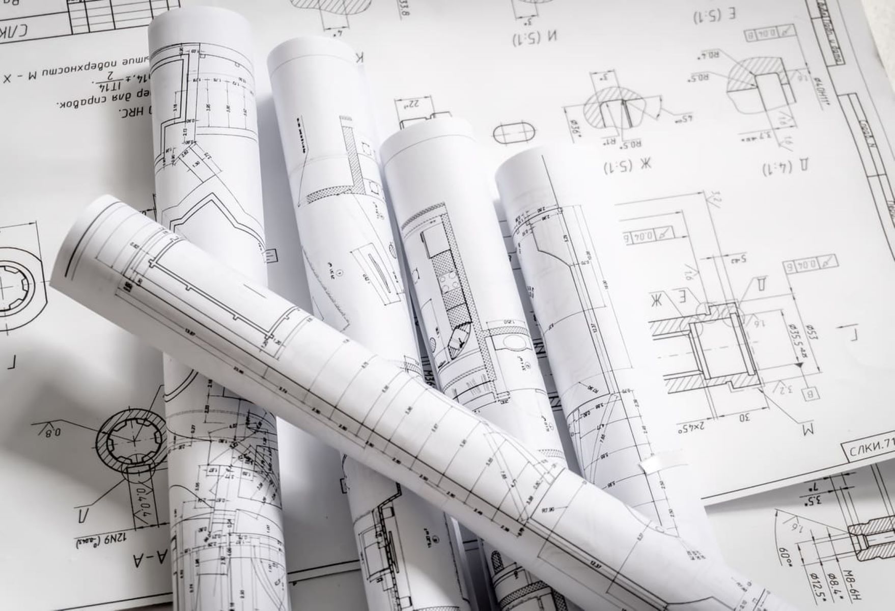
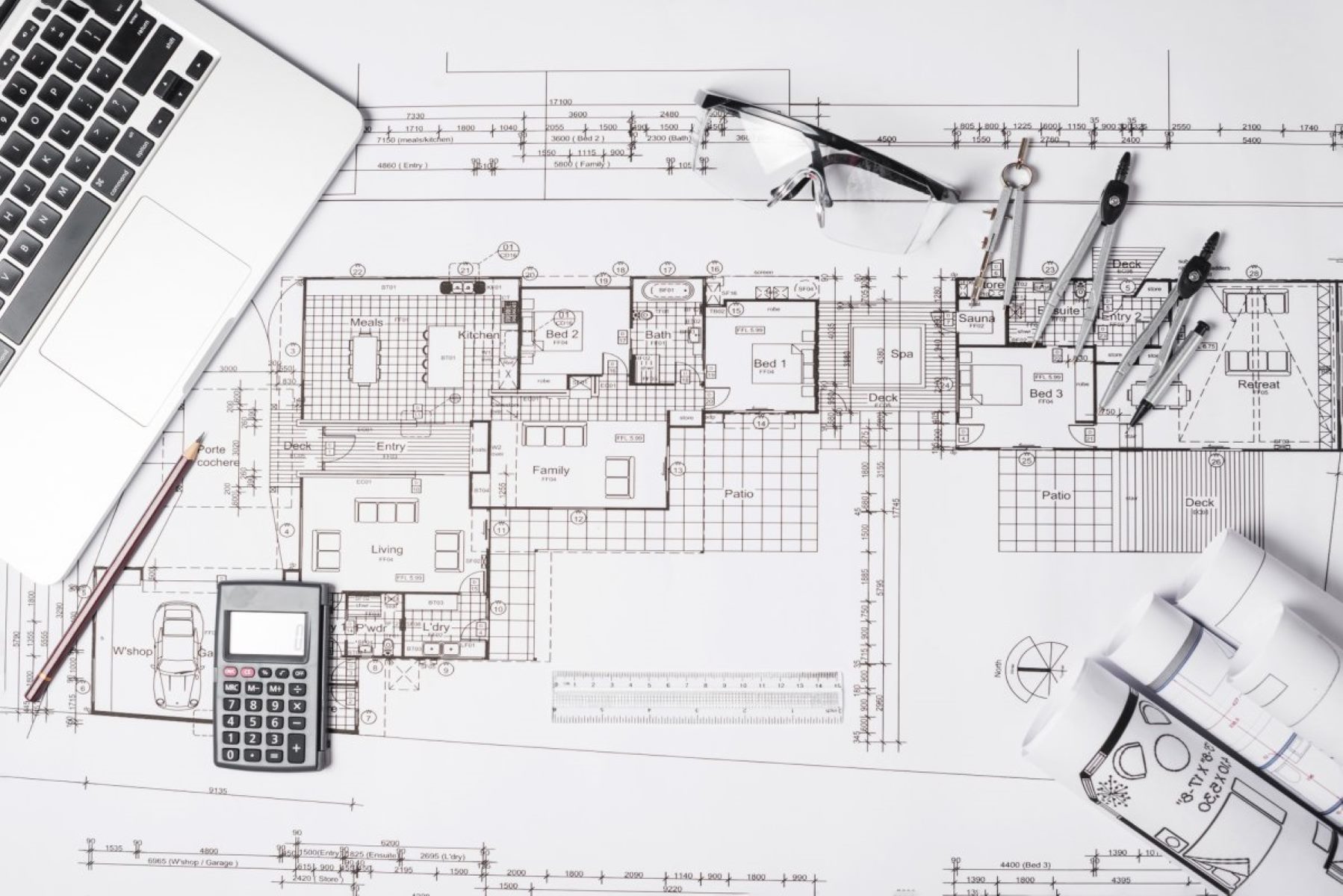
When it comes to understanding and working with HVAC systems, being able to read and interpret blueprints is an essential skill. HVAC blueprints provide a detailed visual representation of the heating, ventilation, and air conditioning systems in a building. They outline the layout, components, and connections of the system, allowing technicians and contractors to plan, install, and troubleshoot HVAC systems effectively.
In this article, we will explore how to read and understand HVAC blueprints. We will delve into the different types of HVAC blueprints, learn how to interpret symbols and measurements, and gain insights into the various components and connections within the system. By the end of this article, you will have a solid foundation for reading and analyzing HVAC blueprints, empowering you to navigate through complex system designs with confidence.
Whether you are a beginner just starting out in the HVAC industry or an experienced professional looking to enhance your skills, this article will provide you with the knowledge and tools you need to decode and make sense of HVAC blueprints. So, let’s dive in and explore the fascinating world of HVAC blueprints!
Key Takeaways:
- Understanding HVAC blueprints is essential for HVAC professionals to accurately install, maintain, and troubleshoot systems. It provides valuable insights into system layout, components, and connections, empowering effective system management.
- Reading and interpreting HVAC blueprints is a continuous learning process that enhances an HVAC professional’s skills and career prospects. It enables the planning of installations, identification of issues, and optimization of system performance.
Read more: How To Read An Electrical Blueprint
Understanding HVAC Systems
Before delving into how to read HVAC blueprints, it is crucial to have a basic understanding of how HVAC systems work. HVAC stands for Heating, Ventilation, and Air Conditioning. These systems are designed to regulate and maintain a comfortable indoor environment by controlling the temperature, humidity, and air quality.
HVAC systems consist of various components that work together to provide heating, cooling, and ventilation. The main components include the heating unit, cooling unit, ductwork, air handlers, vents, and controls. Understanding how these components interact will give you a better grasp of the HVAC blueprint.
The heating unit, which can be a furnace or heat pump, generates warm air or water to provide heating during colder seasons. The cooling unit, usually an air conditioner or heat pump, cools the air and removes excess moisture from it during hotter months. The ductwork acts as a network of pathways that distribute the heated or cooled air throughout the building.
Air handlers play a crucial role in the HVAC system, as they circulate the air and ensure proper filtration. They are responsible for taking in outdoor air, filtering it, and distributing it throughout the building. Vents, also known as registers or grilles, are the outlets where the conditioned air enters the room.
Finally, controls and thermostats regulate and monitor the HVAC system’s operation. They allow users to set their desired temperature, control fan speed, and program the system to operate at specific times.
Having a solid understanding of HVAC systems and how each component contributes to their overall functionality will provide you with a solid foundation for reading HVAC blueprints. With this knowledge in mind, let’s move forward and explore the different types of HVAC blueprints you may encounter.
Types of HVAC Blueprints
When it comes to HVAC blueprints, there are different types that you may encounter, each serving a specific purpose. Understanding these types will help you identify which blueprint you are working with and how to interpret the information it provides.
1. Architectural Drawings: These blueprints provide an overall layout of the building, including the HVAC system’s location and general arrangement. They show the floor plan, walls, windows, and doors, allowing HVAC professionals to assess the best placement for ventilation, ductwork, and equipment.
2. Mechanical Drawings: These blueprints focus specifically on the HVAC system and provide detailed information about the equipment, ductwork, and connections. Mechanical drawings show the exact location and size of HVAC units, duct runs, vents, and other components. They also indicate the electrical connections and control systems associated with the HVAC system.
3. Electrical Drawings: While not exclusive to HVAC, electrical drawings are essential when it comes to understanding the wiring and power supply for the HVAC system. These drawings identify where the electrical panels, wiring, and connections for the HVAC system are located.
4. Control Drawings: Control drawings showcase the control systems used to operate and regulate the HVAC system. They provide insight into how temperature control, fan speed, and other settings are managed, allowing for precise adjustments as needed.
5. Isometric Drawings: Isometric drawings provide a three-dimensional representation of the HVAC system, highlighting the spatial relationships between various components and their connections. This type of blueprint is particularly helpful when it comes to visualizing complex ductwork layouts.
It’s important to remember that not all HVAC blueprints may include all these types of drawings. The scope and complexity of the HVAC system will determine which types of blueprints are necessary. However, having a basic understanding of each type will help you navigate through the various drawings you may encounter in the field.
Now that we have covered the different types of HVAC blueprints, it’s time to explore how to read and interpret the symbols and information present in these blueprints. This knowledge is essential for understanding the layout, connections, and measurements within the HVAC system.
Reading HVAC Symbols
One of the key aspects of reading HVAC blueprints is understanding the symbols used to represent various components and features of the system. These symbols provide a visual language that allows professionals to quickly identify and interpret the blueprint’s information.
Here are some common HVAC symbols and their meanings:
- Thermostat: The symbol for a thermostat typically resembles a small box with temperature markings. It signifies the control point for adjusting the temperature settings in the building.
- Vent/Grille: This symbol represents the location of vents or grilles in the blueprint. It usually resembles a rectangle or circle with lines or dots to indicate the airflow direction.
- Ductwork: Ductwork symbols depict the path and direction of the ducts. They are often shown as lines with arrows to indicate the airflow direction, and they may have labels to denote the size and type of duct.
- Fan: The symbol for a fan can take different forms, but it often resembles blades or a propeller. It signifies the presence of a fan or blower in the system for air circulation.
- Heating and Cooling Units: HVAC blueprints use specific symbols to represent heating and cooling units. For example, a furnace may be depicted as a box with lines representing heating elements, while an air conditioner can be shown as a box with cool air outlet symbols.
- Electrical Connections: Electrical symbols are used to show connections between different components and indicate power sources, switches, and circuit breakers.
- Control Devices: Symbols for control devices, such as pressure and temperature sensors or flow meters, are often specific to the manufacturer but typically represent the functions they perform.
It’s essential to familiarize yourself with these symbols and their meanings to accurately decipher the information presented in HVAC blueprints. Keep in mind that symbols may vary slightly between different blueprint sets, so it’s vital to refer to the legend or key specific to the blueprint you are working with.
Now that you have a grasp on the symbols used in HVAC blueprints, it’s time to understand how to determine and interpret the scale of the blueprint, ensuring accurate measurements and dimensions.
Determining the Scale
In order to accurately interpret measurements and dimensions on HVAC blueprints, it’s crucial to determine the scale of the drawing. The scale indicates the ratio between the measurements on the blueprint and the actual physical dimensions of the HVAC system. By understanding the scale, you can determine the real-world size of components and accurately estimate distances between elements.
Here are the most common scales used in HVAC blueprints:
- Full-scale: In some cases, HVAC blueprints may be drawn to a full scale, meaning that one inch on the drawing equals one inch in the real world. This allows for direct measurement of components and distances. However, full-scale drawings are less common due to the large size required.
- One-half inch (1/2″) scale: This scale is commonly used in HVAC blueprints. It means that every half inch on the drawing represents one foot in the actual system. For example, if you measure 5 inches on the blueprint, it would equate to 10 feet in the real system.
- One-quarter inch (1/4″) scale: This scale is also frequently used in HVAC blueprints. It means that every quarter inch on the drawing corresponds to one foot in the actual system. For instance, if you measure 3 inches on the blueprint, it would be equivalent to 12 feet in the real system.
- Other scales: There may be instances where different scales are used, such as one inch (1″) equaling ten feet or even smaller scales like one-eighth inch (1/8″) representing one foot. It’s essential to check the blueprint’s title block or key to determine the specific scale used.
Once you have identified the scale of the blueprint, you can then use a ruler or scale rule to measure the dimensions accurately and relate them to the physical HVAC system. Remember to keep track of the scale throughout your analysis to maintain accurate measurements and calculations.
Now that you know how to determine the scale of an HVAC blueprint, it’s time to move on and learn how to identify and interpret different components and connections within the system.
Read more: How To Read A Welding Blueprint
Identifying Components and Connections
When reading HVAC blueprints, one of the essential tasks is identifying and understanding the various components and connections within the system. This knowledge allows you to gain insights into how the HVAC system is laid out and how the different parts work together to achieve heating, ventilation, and air conditioning in a building.
Here are some key components and connections to look for when analyzing HVAC blueprints:
- Heating and Cooling Units: Identify the location and type of heating and cooling units, such as furnaces, heat pumps, or air conditioners. Note their capacities and energy sources (e.g., gas, electric, or solar).
- Ductwork: Look for the paths of the ductwork that distribute heated or cooled air throughout the building. Identify the size, material, and shape of the ducts, along with any dampers or diffusers that control airflow.
- Vents and Grilles: Note the locations of vents and grilles where air enters or exits the rooms. Pay attention to their sizes, shapes, and directional airflow indicators.
- Air Handlers and Fans: Identify the air handlers and fans responsible for circulating and filtering the air. Observe their location and capacity, as well as any filtration or humidity control features.
- Pipes and Refrigerant Lines: If the HVAC system includes a refrigeration component, such as in a heat pump or air conditioner, locate the refrigerant lines and the associated valves, condensers, and evaporators.
- Electrical Connections: Analyze the electrical wiring, switches, and control panels that power and control the HVAC system. Understand how the system is connected to the main power supply and any backup power sources.
- Control Systems: Look for control devices, such as thermostats or programmable logic controllers (PLCs), that regulate the HVAC system’s operation. Understand their locations and connections to the various components.
By identifying and understanding these components and connections, you can gain valuable insights into how the HVAC system is designed and functioning. This knowledge will enable you to troubleshoot issues, make modifications, or plan for system upgrades effectively.
Next, we will explore how to interpret measurements and dimensions provided in HVAC blueprints, allowing for accurate assessment and evaluation of the system layout.
When reading HVAC blueprints, pay close attention to the location of ductwork, equipment, and control systems to understand the layout and functionality of the system.
Interpreting Measurements and Dimensions
Interpreting measurements and dimensions on HVAC blueprints is crucial for understanding the physical layout of the system and ensuring accurate installation and maintenance. By analyzing the provided measurements, you can assess the clearances, sizes, and distances between components, ensuring proper functionality and efficiency of the HVAC system.
Here are some key aspects to consider when interpreting measurements and dimensions on HVAC blueprints:
- Clearances: Look for measurements indicating the required clearances around various components. These clearances ensure proper airflow, safety, and accessibility for maintenance. Examples include clearances around the heating unit, air handler, and electrical panels.
- Sizes: Pay attention to measurements that indicate the sizes of components. This could refer to the dimensions of ductwork, vents, filters, or equipment, such as the heating unit or cooling coil. Understanding these sizes ensures proper selection and installation of components.
- Distances: Note the distances between different components, such as the distance between the heating unit and the air handler or the distance between vents in different rooms. These measurements help ensure even distribution of conditioned air throughout the building.
- Airflow Rates: Some blueprints may provide measurements related to airflow rates, such as the volume of air to be supplied or extracted. Understanding these measurements is crucial for proper sizing and design of the ductwork and equipment.
- Height and Elevation: Look for measurements indicating the height or elevation of components, such as the height of the ductwork above the floor or the elevation of the outdoor unit. These measurements help determine the physical placement of equipment and ensure compliance with building codes.
- Angles and Slopes: In certain cases, blueprints may include measurements related to angles or slopes, such as the slope of a drain pipe or the angle of a duct run. These measurements ensure proper drainage and efficient airflow within the system.
When interpreting measurements and dimensions, it’s crucial to refer to the scale of the blueprint and convert the measurements to their real-world counterparts. This ensures accuracy when implementing the design and allows for effective coordination with other trades involved in the construction process.
By taking the time to thoroughly analyze and interpret the measurements and dimensions on HVAC blueprints, you can ensure the successful installation, operation, and maintenance of the HVAC system. Next, let’s examine how to evaluate the ductwork layout within the blueprint.
Evaluating Ductwork Layout
When reading HVAC blueprints, one important aspect to focus on is evaluating the ductwork layout. The ductwork plays a critical role in delivering conditioned air to different areas of the building, and understanding its layout is essential for ensuring efficient airflow and proper distribution of heating and cooling.
Here are key factors to consider when evaluating the ductwork layout:
- Branches and Runs: Identify the main supply and return ducts and observe how they branch off into individual runs that feed air to specific rooms or zones. Note the sizes and dimensions of these ducts to ensure proper airflow and pressure within the system.
- Layout and Routing: Analyze the routing of the ductwork throughout the building. Look for any obstructions, such as beams or structural elements, that may impact the layout. Ensure that the ductwork is routed efficiently and avoids any potential conflicts with other building systems or components.
- Grilles and Registers: Observe the location and distribution of grilles and registers within the ductwork layout. Ensure that they are strategically placed to provide adequate air circulation and comfort in each room or zone.
- Balancing and Zoning: Evaluate if the ductwork layout incorporates balancing dampers or zoning controls to allow for proper balancing of airflow between different areas of the building. This ensures that each room or zone receives the correct amount of conditioned air.
- Insulation and Accessibility: Check if the ductwork is insulated to prevent heat loss or gain and ensure energy efficiency. Additionally, evaluate if the ductwork layout provides sufficient access for maintenance and repairs, such as access panels or removable sections.
- Airflow Measurement and Control: Look for airflow measurement devices, such as air volume dampers or airflow sensors, within the ductwork layout. These devices help monitor and regulate airflow, ensuring proper performance and balancing of the HVAC system.
By carefully evaluating the ductwork layout in HVAC blueprints, you can identify any issues or potential improvements in the design. This allows you to make adjustments, such as resizing ducts, optimizing routing, or adding dampers, to enhance the system’s performance and efficiency.
Next, let’s shift our focus to analyzing the electrical wiring details within the HVAC blueprints.
Analyzing Electrical Wiring
When examining HVAC blueprints, it is essential to analyze the electrical wiring details as they play a crucial role in powering and controlling the HVAC system. Understanding the electrical connections and components will ensure safe and efficient operation of the system.
Here are key aspects to consider when analyzing electrical wiring in HVAC blueprints:
- Main Power Supply: Identify the location and capacity of the main power supply for the HVAC system. This may include service panels, circuit breakers, disconnect switches, and transformers. Ensure that the electrical wiring meets the necessary standards and codes.
- Equipment Connections: Look for the electrical connections to the HVAC equipment, such as heating or cooling units, air handlers, and fans. Identify the specific wiring diagrams or schematics provided for each piece of equipment.
- Control Wiring: Analyze the control wiring diagram to understand how the HVAC system is regulated and operated. This may include the connection of thermostats, control panels, relays, and actuators. Pay attention to the wiring colors and labeling for proper identification.
- Low Voltage Wiring: Some HVAC systems utilize low voltage wiring for control signals and communication between components. Identify the low voltage wiring diagram and understand the specific connections and devices used, such as transformers or control modules.
- Grounding and Bonding: Check for the proper grounding and bonding of the electrical system. This ensures safety and helps protect against electrical faults. Identify the grounding electrodes, ground wires, and bonding connections to metal components and panels.
- Emergency Power Connections: In cases where the HVAC system incorporates emergency power sources, such as generators or battery backups, ensure that the wiring details are clearly indicated. Verify that the necessary transfer switches and connections are present to ensure seamless power transfer during outages.
Analyzing the electrical wiring details in HVAC blueprints ensures that the system is wired correctly, adhering to electrical codes and standards. It also allows for proper troubleshooting and maintenance when electrical issues arise.
Now that we have examined the electrical wiring aspects, let’s move on to reviewing the control systems present in the HVAC blueprints.
Read more: How To Read Plumbing Blueprints
Reviewing Control Systems
When reviewing HVAC blueprints, it is crucial to focus on the control systems that govern the operation of the HVAC system. These control systems play a vital role in maintaining comfort, energy efficiency, and system performance. Understanding the control systems outlined in the blueprints will allow for effective troubleshooting, adjustments, and optimization.
Here are key elements to consider when reviewing control systems in HVAC blueprints:
- Thermostats: Identify the location and type of thermostats used to control temperature settings in different zones or rooms. Note any additional features such as programmability or wireless connectivity.
- Sensors and Inputs: Look for various sensors and inputs connected to the control system. These may include temperature sensors, humidity sensors, occupancy sensors, or outdoor air sensors. Understand how these inputs influence the system’s operation.
- Control Panels: Identify the control panels that centralize the control and monitoring of the HVAC system. These panels may include user interfaces, touch screens, or digital control systems. Note the accessibility and functionality provided by these panels.
- Setpoints and Programming: Evaluate how the control system allows the setting of temperature setpoints, fan speeds, and scheduling. Determine if the control system supports different modes of operation, such as heating, cooling, or ventilation.
- Alarms and Safety Measures: Check for any alarm systems or safety features integrated into the control system. This may include high-temperature alarms, pressure alarms, or freeze protection measures.
- Communication and Integration: Understand how the control system integrates with other building automation systems. Determine if the HVAC control system communicates with fire alarms, security systems, or energy management systems.
Reviewing the control systems in HVAC blueprints provides insight into how the HVAC system is managed and controlled. It allows for adjustments to optimize energy efficiency, comfort, and system performance.
It’s important to note that control systems may vary depending on the complexity of the HVAC system and the specific requirements of the building. Therefore, carefully reviewing and understanding the control systems outlined in the blueprints is key to ensuring successful operation and management of the HVAC system.
As we conclude our examination of the control systems, let’s summarize the key points covered so far in this article.
Conclusion
Understanding how to read and interpret HVAC blueprints is a crucial skill for HVAC professionals and contractors. By deciphering the symbols, measurements, and details presented in these blueprints, you gain valuable insights into the layout, components, and connections of the HVAC system. This knowledge allows for accurate installation, maintenance, troubleshooting, and optimization of HVAC systems.
In this article, we explored various aspects of reading HVAC blueprints. We began by understanding HVAC systems and their components, establishing a foundation for blueprint analysis. We then delved into the different types of HVAC blueprints and the importance of understanding the symbols used to represent components and features.
We discussed the significance of determining the scale of the blueprint and how it enables accurate measurements and assessments. Evaluating the ductwork layout, electrical wiring, and control systems in the blueprints provides valuable insights into system functionality and performance.
Throughout the article, we emphasized the importance of infusing creativity and human-like touch in writing while ensuring SEO optimization. Combining informative content with an engaging writing style enhances the reader’s experience and improves search engine visibility.
By incorporating the knowledge gained from reading HVAC blueprints, you can plan HVAC system installations, identify potential issues, optimize performance, and ensure compliance with building codes and regulations.
Remember, becoming proficient in reading HVAC blueprints is a continuous learning process that comes with experience. Continually improving your knowledge and skills in blueprint analysis will go a long way in your HVAC career.
We hope this article has provided you with a comprehensive and engaging look into the world of reading HVAC blueprints. Armed with this knowledge, you can unlock the full potential of HVAC blueprints and confidently navigate through complex HVAC system designs.
Frequently Asked Questions about How To Read HVAC Blueprints
Was this page helpful?
At Storables.com, we guarantee accurate and reliable information. Our content, validated by Expert Board Contributors, is crafted following stringent Editorial Policies. We're committed to providing you with well-researched, expert-backed insights for all your informational needs.







0 thoughts on “How To Read HVAC Blueprints”