Articles
How To Read Plumbing Blueprints
Modified: August 17, 2024
Learn how to read plumbing blueprints with our comprehensive articles. Gain the knowledge and skills needed to understand complex diagrams and effectively plan your plumbing projects.
(Many of the links in this article redirect to a specific reviewed product. Your purchase of these products through affiliate links helps to generate commission for Storables.com, at no extra cost. Learn more)
Introduction
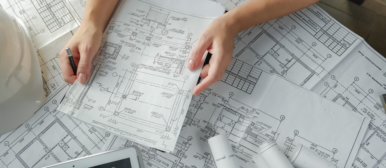
Welcome to the world of plumbing blueprints! If you’re a homeowner, contractor, or aspiring plumber, understanding plumbing blueprints is an essential skill to have. These blueprints provide detailed information about the layout and design of the plumbing system in a building, enabling professionals to install, repair, and maintain it effectively.
While plumbing blueprints may seem complex and intimidating at first glance, they follow specific conventions and use universally recognized symbols and abbreviations. With a little bit of knowledge and practice, you can decipher these blueprints and gain a deeper understanding of the plumbing system in any building.
In this article, we will guide you through the process of reading plumbing blueprints and help you understand the key symbols, abbreviations, dimensions, and other important aspects. With this knowledge, you’ll be equipped to navigate and interpret plumbing blueprints with ease.
Before we dive into the details, it’s important to note that plumbing blueprints are typically part of a larger set of construction drawings. These drawings include architectural plans, electrical schematics, and mechanical systems, among others. Plumbing blueprints specifically focus on the installation and layout of pipes, fixtures, and other components related to the plumbing system.
So, whether you’re looking to better understand the plumbing system in your own home or you’re interested in pursuing a career in plumbing, let’s start our journey into the world of plumbing blueprints!
Key Takeaways:
- Mastering the art of reading plumbing blueprints empowers homeowners and professionals to understand, troubleshoot, and contribute to the successful completion of plumbing projects, enhancing knowledge and skills in the field.
- Familiarizing oneself with key symbols, abbreviations, dimensions, and annotations in plumbing blueprints provides a solid foundation for deciphering the layout, design, and functionality of the plumbing system in any building.
Read more: How To Read An Electrical Blueprint
Understanding Plumbing Blueprints
Plumbing blueprints are detailed graphical representations of the plumbing system in a building. They provide vital information to contractors, plumbers, and other professionals involved in the construction or renovation process. Understanding plumbing blueprints is essential for accurate installation, troubleshooting, and repairs.
At first glance, plumbing blueprints may appear overwhelming with their complex diagrams, symbols, and measurements. However, with a little knowledge and practice, you can decipher these blueprints and gain a deeper understanding of the plumbing system.
Before we delve into the specifics, it’s important to understand the basic layout of plumbing blueprints. Typically, plumbing blueprints are drawn on a scale, with each square on the drawing representing a specific unit of measurement, such as inches or feet. The blueprints consist of a series of plans, elevations, sections, and details, providing a comprehensive view of the entire plumbing system.
The plans illustrate the horizontal view of the plumbing system, giving you an idea of how the pipes, fixtures, and appliances are laid out in the building. The elevations show the vertical view, revealing the heights and placements of various components. The sections provide a cut-away view, allowing you to see the internal details of the plumbing system. The details highlight specific areas or components in greater detail.
In addition to the graphical representation of the plumbing system, plumbing blueprints include key symbols and abbreviations that convey important information. These symbols and abbreviations are standardized and widely recognized in the plumbing industry. Familiarizing yourself with these symbols is crucial for accurately interpreting the blueprints.
Furthermore, it’s important to note that plumbing blueprints can vary depending on the type of building and local building codes. For example, residential plumbing blueprints may differ from commercial or industrial ones. Additionally, local building codes may dictate specific requirements for venting, drainage, and water supply. Therefore, it’s advisable to consult the local building authority to ensure compliance.
Now that you have a basic understanding of plumbing blueprints, let’s move on to exploring the key symbols and abbreviations used, and how to read dimensions and measurements on these blueprints.
Key Symbols and Abbreviations
Plumbing blueprints rely on a standardized set of symbols and abbreviations to represent various components, fixtures, and system elements. These symbols serve as a visual language that allows professionals to quickly understand the intended design and layout of the plumbing system.
Here are some of the key symbols and abbreviations used in plumbing blueprints:
- W: Represents water supply lines. These lines carry clean, potable water from the main source to the various fixtures and appliances in the building.
- D: Indicates drainage lines. These pipes carry wastewater and other liquid waste away from the fixtures and appliances to the main sewer line or septic system.
- V: Stands for vent pipes. These pipes allow air to enter the drainage system, preventing suction and ensuring smooth flow of wastewater.
- S: Represents sewer lines. These pipes carry wastewater from the building to the municipal sewer system or septic tank.
- WC: Represents water closet, which is a toilet fixture.
- LAV: Stands for lavatory, which typically refers to a bathroom sink.
- SHWR: Represents a shower fixture.
- TUB: Indicates a bathtub fixture.
- FAUCET: Represents a faucet or tap.
- HWT: Stands for hot water tank, which is a storage tank for hot water.
- HW: Indicates a hot water supply line.
- HWV: Represents a hot water vent pipe.
These symbols are typically accompanied by directional arrows, numbers, and letters to provide additional information about the flow, size, and material of the pipes. It’s important to familiarize yourself with these symbols and their meanings to accurately interpret the plumbing blueprints.
In addition to symbols, abbreviations are commonly used in plumbing blueprints to convey information concisely. Here are some frequently used abbreviations:
- GPM: Stands for gallons per minute, indicating the water flow rate.
- CFM: Represents cubic feet per minute, used to measure the air flow rate.
- OD: Stands for outside diameter, used to specify the size of pipes and fittings.
- BSMT: Indicates basement.
- 1F: Represents the first floor of the building.
- 2F: Indicates the second floor.
- 3F: Represents the third floor.
- UR: Stands for upper roof.
- VAL: Represents a valve.
- EL: Stands for elevation.
By familiarizing yourself with these symbols and abbreviations, you will be able to decipher the plumbing blueprints with ease and understand the intended design and layout of the plumbing system.
Reading Dimensions and Measurements
One of the key aspects of understanding plumbing blueprints is being able to read and interpret dimensions and measurements accurately. Dimensions provide crucial information about the size, length, and height of pipes, fixtures, and other components in the plumbing system.
Here are some important guidelines to help you read dimensions and measurements on plumbing blueprints:
- Scale: Plumbing blueprints are typically drawn to a specific scale, such as 1/4″ = 1 foot or 1/8″ = 1 foot. This means that every inch on the drawing represents a certain number of feet in the actual building. Make sure to identify the scale used and keep it in mind while reading dimensions.
- Units of Measurement: Dimensions on plumbing blueprints are commonly expressed in feet (ft), inches (in), and fractions of an inch. Familiarize yourself with commonly used fractions and their decimal equivalents to accurately interpret the measurements.
- Length and Distance: Dimensions indicating the length or distance between two points are typically represented by a horizontal line with arrows at both ends. The dimension value is usually written above or below the line, specifying the length in the chosen units of measurement.
- Height: Heights of fixtures, pipes, and other components are often represented by a vertical line with arrows at both ends. The dimension value is written next to the line, indicating the height from a specific reference point.
- Diameter: Pipe diameters are typically represented by a circle or a circle with a diagonal line through it. The dimension value is written inside or next to the circle, indicating the diameter of the pipe in inches or fractions of an inch.
- Arcs and Angles: Curved pipes or angled sections are represented by arcs or lines with angles indicated. The dimension values for arcs represent the radius or diameter, while angles are specified in degrees.
- Tolerances: Some dimensions may have tolerances specified, indicating the acceptable range of variation. Tolerances are typically represented with a plus or minus symbol (+/-) followed by a value.
It’s important to pay attention to the scales, units of measurement, and reference points provided in the plumbing blueprints. By carefully reading and interpreting the dimensions, you can accurately assess the size and position of various plumbing system components.
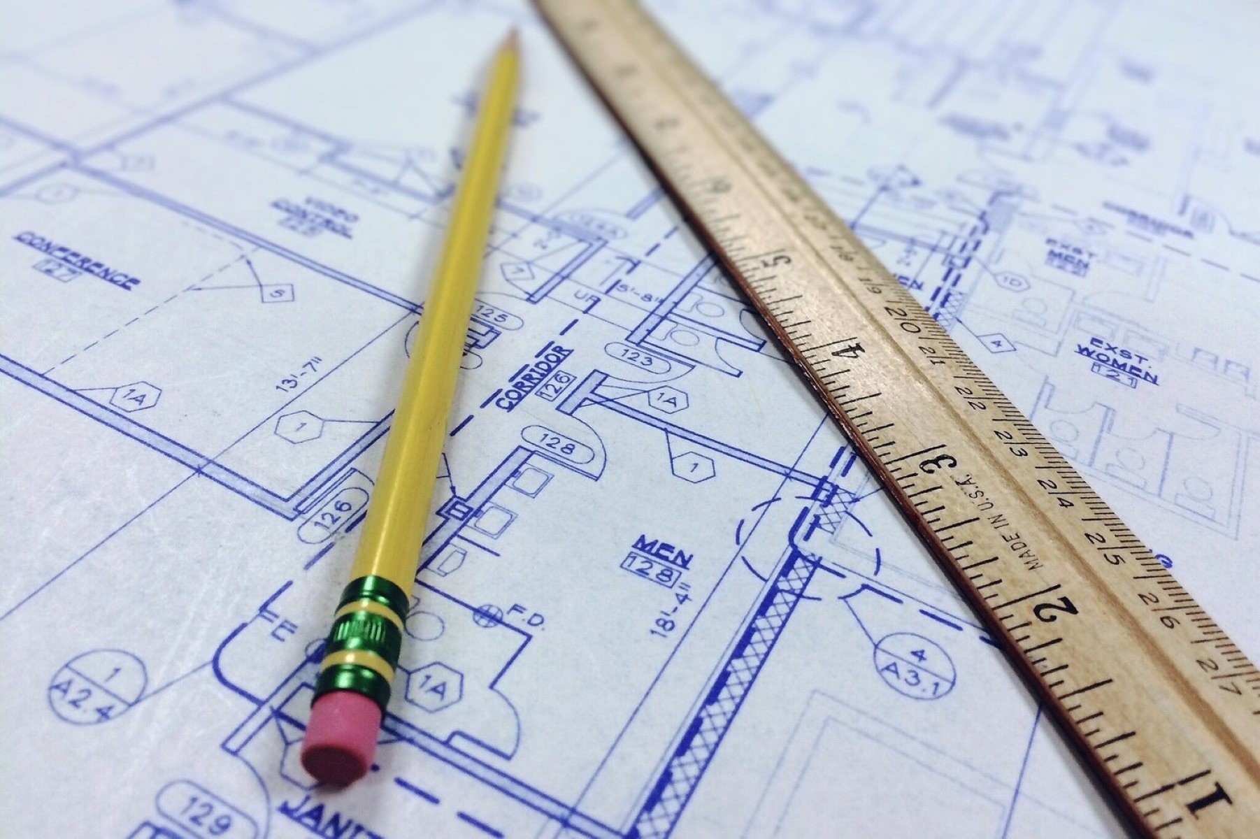
When working with plumbing blueprints, it’s also useful to have a measuring tape or ruler handy. You can use these tools to compare the scale on the blueprint and take measurements on-site, ensuring accuracy during installation or repair work.
Now that you understand how to read and interpret dimensions and measurements on plumbing blueprints, let’s move on to identifying plumbing fixtures and appliances.
Identifying Plumbing Fixtures and Appliances
In plumbing blueprints, various fixtures and appliances are represented using specific symbols and annotations. Identifying these plumbing fixtures and appliances is crucial for understanding the layout and function of the plumbing system. Let’s explore some common plumbing fixtures and appliances and how they are depicted on blueprints:
- Toilets: Toilets are commonly represented by a circle with a small triangle inside, indicating the bowl and tank. The symbol may be accompanied by the abbreviation “WC” (water closet) or a label indicating the number of toilets present in a specific area.
- Sinks: Bathroom and kitchen sinks are often represented by a circle or oval shape with a small line that denotes the faucet. The symbol may be accompanied by the abbreviation “LAV” (lavatory).
- Shower: Showers are typically represented by a circle or rectangle with horizontal lines that indicate the showerhead. The symbol may be accompanied by the abbreviation “SHWR”.
- Bathtubs: Bathtubs are represented as a rectangular shape with rounded corners. The symbol may have an internal line or an oval shape that denotes the drain. The abbreviation “TUB” is often used alongside the symbol.
- Faucets: Faucets or taps are depicted as small circles or squares with lines indicating the flow of water. The symbols may vary depending on the specific type of faucet, such as a kitchen faucet or bathroom faucet.
- Water Heaters: Water heaters are typically shown as rectangular shapes with annotations for the type, capacity, and location. The abbreviation “HWT” (hot water tank) is often used alongside the symbol.
- Washing Machines and Dishwashers: These appliances are represented by rectangular shapes with horizontal lines or other symbols denoting the water connections. Annotations may indicate the type and location of the appliance.
It’s important to note that the symbols used for plumbing fixtures and appliances may vary slightly depending on the specific plumbing blueprint or regional conventions. However, these representations provide a general guide to identifying and understanding the various components of the plumbing system.
In addition to the symbols, annotations and labels on plumbing blueprints provide specific information about the location, type, and quantity of each fixture or appliance. These annotations may include abbreviations, reference numbers, or additional notes to clarify the details of the plumbing system.
By familiarizing yourself with the symbols and annotations used to represent plumbing fixtures and appliances, you will have a better understanding of the layout and functionality of the plumbing system depicted in the blueprints.
Now that we’ve identified the plumbing fixtures and appliances, let’s move on to interpreting pipe routing and connections in plumbing blueprints.
Look for the plumbing legend to understand the symbols and abbreviations used in the blueprints. This will help you interpret the layout and connections of the plumbing system.
Read more: How To Read A Welding Blueprint
Interpreting Pipe Routing and Connections
Understanding the routing and connections of pipes is essential for comprehending plumbing blueprints. It provides insight into how water flows throughout the building and how different fixtures and appliances are connected. Let’s explore how to interpret pipe routing and connections in plumbing blueprints:
1. Pipe Routing: The routing of pipes in plumbing blueprints is represented by lines of various thicknesses and types. Generally, solid lines indicate primary pipes, while dashed or dotted lines represent secondary or auxiliary pipes. The direction of the lines shows the flow of water, with arrows indicating the intended flow direction. It’s important to follow the flow direction when installing or making connections between pipes.
2. Pipe Connections: Pipe connections are depicted using specific symbols or annotations that indicate the type of connection. Here are some common pipe connection symbols:
- Tee Connection: A tee connection is represented by a T-shaped symbol, which signifies the merging of two pipes into one perpendicular pipe.
- Elbow Connection: An elbow connection is shown as a curved or angled line, indicating a change in the direction of the pipe.
- Coupling Connection: A coupling connection is represented by a straight line, indicating the joining of two pipes end-to-end.
- Valve Connection: Valves are usually depicted by a circle or a square symbol with an internal line, indicating the flow control function. Annotations may provide additional information about the type and purpose of the valve, such as a shutoff valve or a pressure regulator.
It’s important to pay attention to the size and materials of the pipes indicated on the blueprints. Pipe sizes are typically labeled with annotations that specify the diameter or dimensions of the pipes. Material annotations may indicate the type of pipe material used, such as copper, PVC (polyvinyl chloride), or PEX (cross-linked polyethylene).
Additionally, be aware of venting and drainage systems, which play a crucial role in the plumbing system. Vent pipes are typically represented by smaller dashed lines that extend vertically from the drainage pipes. These pipes allow air to enter the system, facilitating the smooth flow of wastewater. Drainage lines are represented by solid lines that connect to the fixtures and appliances, leading the wastewater towards the main sewer line or septic system.
By understanding the routing and connections of pipes, you can visualize how the water travels through the plumbing system and how various fixtures and appliances are interlinked. This knowledge is vital for ensuring proper installation, maintenance, and troubleshooting of the plumbing system.
Next, let’s explore how to recognize venting and drainage systems in plumbing blueprints.
Recognizing Venting and Drainage Systems
While reading plumbing blueprints, it’s crucial to recognize the venting and drainage systems. These systems are essential components of the plumbing system and play a vital role in maintaining proper operation and preventing issues such as clogs and sewer gas buildup. Understanding the venting and drainage systems in the blueprints will help you ensure that the plumbing system functions effectively. Let’s explore how to recognize these systems:
1. Venting System: Vent pipes are an integral part of the plumbing system and are responsible for venting out sewer gases and providing air pressure balance within the drainage system. In plumbing blueprints, vent pipes are often depicted as dashed lines that extend vertically from the drainage pipes. These lines may connect to the main vent stack or extend through the roof of the building. It’s important to identify the vent pipes and their connections to ensure that proper venting is maintained throughout the plumbing system.
2. Drainage System: The drainage system carries wastewater and other liquid waste away from the fixtures and appliances in the building. In plumbing blueprints, drainage pipes are typically represented as solid lines that connect the fixtures and appliances to the main sewer line or septic system. These pipes may be labeled with annotations indicating their sizes, materials, and slope. It’s important to recognize the drainage system and ensure that the pipes are properly connected and sloped to allow for efficient wastewater flow.
In addition to the venting and drainage systems, plumbing blueprints may also include other components related to the plumbing system, such as cleanouts, backflow preventers, and traps. Cleanouts are access points that allow for easy maintenance and removal of clogs in the drainage system. Backflow preventers are valves that prevent the reverse flow of water, ensuring that contaminated water does not mix with the clean water supply. Traps are curved sections of pipes that retain water, forming a barrier against sewer gases and preventing them from entering the building.
By recognizing and understanding the venting and drainage systems in plumbing blueprints, you can ensure the proper functioning of the plumbing system and prevent potential issues such as sewer gas odors, clogs, and backflow. It’s essential to adhere to local building codes and regulations regarding venting and drainage systems to maintain the safety and integrity of the plumbing system.
Next, let’s explore how to analyze water supply lines in plumbing blueprints.
Analyzing Water Supply Lines
Water supply lines are a critical component of the plumbing system, providing clean and potable water to various fixtures and appliances in a building. Analyzing the water supply lines on plumbing blueprints is essential for understanding the layout and distribution of water throughout the plumbing system. Let’s explore how to analyze water supply lines:
1. Main Water Supply Line: The main water supply line is the primary pipe that brings water into the building from the municipal water source or a well. In plumbing blueprints, the main water supply line is typically represented by a solid line that enters the building at a designated point. Annotations may indicate the size and material of the pipe.
2. Branch Lines: Branch lines are secondary water supply lines that distribute water from the main supply line to various fixtures and appliances. These lines are typically represented by solid lines that connect to the main supply line and extend to different areas of the building. Annotations may indicate the size and material of the pipe, as well as the type of fixture or appliance it serves.
3. Fixture Connections: Water supply lines connect to individual fixtures and appliances, such as sinks, showers, toilets, and washing machines. These connections are represented by solid lines that extend from the branch lines to the fixtures. The lines may be labeled with annotations indicating the type of fixture and fixture symbol. These symbols could include abbreviations such as “LAV” for lavatory or “WC” for water closet.
4. Shut-off Valves: Shut-off valves are an important component of water supply lines as they allow for isolation and control of water flow to specific fixtures or areas of the building. On plumbing blueprints, shut-off valves are often represented by symbols, such as circles or squares with an internal line. Annotations may provide additional information about the type and location of the valve.
It’s important to analyze the water supply lines on plumbing blueprints to ensure that the distribution of water is efficient and meets the requirements of the building. Pay attention to the sizing and materials of the pipes, as well as the placement of shut-off valves, to ensure proper water flow and accessibility for maintenance purposes.
Furthermore, understanding the water supply lines on plumbing blueprints is crucial for identifying potential cross-connections, which occur when a non-potable source, such as a wastewater line, accidentally mixes with the clean water supply. Cross-connections can lead to contamination and health hazards. By analyzing the water supply lines, you can ensure the proper installation and prevention of cross-connections in the plumbing system.
Now that we’ve examined the water supply lines, let’s move on to reading plumbing details and notes on blueprints.
Reading Plumbing Details and Notes
In addition to the graphical representations and symbols, plumbing blueprints often include detailed information in the form of written notes and annotations. These details provide important instructions, specifications, and additional information about the plumbing system. Let’s explore how to read plumbing details and notes on blueprints:
1. Specifications: Plumbing details and notes often specify the materials, sizes, and standards that should be followed during the installation or maintenance of the plumbing system. This information ensures compliance with local building codes and regulations. Pay attention to any specific instructions regarding the type of pipes, fittings, or fixtures to be used, as well as any regulations about water pressure, insulation, or accessibility requirements.
2. Special Requirements: Plumbing blueprints may include notes highlighting any special requirements or considerations for certain areas or fixtures. For example, a note may specify the requirement for an air gap between the dishwasher drain and the garbage disposal to prevent backflow. These details ensure that proper precautions are taken to maintain the safety and functionality of the plumbing system.
3. Measurements and Clearances: Plumbing blueprints may include specific measurements and clearances that need to be followed during the installation of pipes, fixtures, or other components. These measurements ensure that there is sufficient space for proper installation and maintenance. Pay attention to any clearances required for fixtures like toilets or sinks, as well as minimum and maximum distances for vent pipes, drain lines, or water supply pipes.
4. Notes on Special Features: Some plumbing blueprints may include notes about special features or custom installations. These could include details about water filtration systems, water softeners, or specialized fixtures such as bidets. These notes provide valuable information for understanding the specific requirements and considerations for these features.
5. Plumbing Codes and Regulations: Plumbing blueprints may reference specific codes or regulations that need to be followed during the installation or maintenance process. These references ensure that the plumbing system complies with industry standards and local building codes. It’s important to be familiar with the plumbing codes and regulations applicable to the specific area to ensure that the plumbing system is safe and up to code.
Reading and understanding plumbing details and notes on blueprints is crucial for ensuring that the plumbing system is installed, maintained, and repaired correctly. These details provide important information and guidelines that help professionals adhere to standards and regulations, resulting in a properly functioning and safe plumbing system.
Now that we’ve covered the reading of plumbing details and notes, let’s conclude our exploration of plumbing blueprints.
Read more: How To Read Construction Blueprints
Conclusion
Congratulations! You have reached the end of our journey through the world of plumbing blueprints. Understanding plumbing blueprints is a valuable skill that allows you to decipher the layout, design, and functionality of the plumbing system in a building. With this knowledge, you can confidently navigate the complexities of plumbing blueprints and effectively work with contractors, plumbers, and other professionals involved in the construction or renovation process.
Throughout this article, we’ve covered various aspects of plumbing blueprints, including key symbols and abbreviations, reading dimensions and measurements, identifying plumbing fixtures and appliances, interpreting pipe routing and connections, recognizing venting and drainage systems, analyzing water supply lines, and reading plumbing details and notes. By familiarizing yourself with these elements, you have gained a solid foundation for understanding plumbing blueprints.
Remember, plumbing blueprints are just one piece of the larger puzzle of construction drawings. They provide essential details about the plumbing system, ensuring its proper installation, functioning, and maintenance. However, it’s important to consult other construction drawings and local building codes to obtain a comprehensive understanding of the entire construction project.
Whether you’re a homeowner looking to better understand your own plumbing system or a professional in the construction or plumbing industry, mastering the art of reading plumbing blueprints will undoubtedly enhance your knowledge, skills, and efficiency in the field. It will empower you to make informed decisions, troubleshoot problems effectively, and contribute to the successful completion of plumbing projects.
So, continue to explore the world of plumbing blueprints, stay updated with industry standards and regulations, and never stop expanding your knowledge. With your newfound understanding of plumbing blueprints, you’ll be well-equipped to navigate the intricate world of plumbing and contribute to the development of safe and functional plumbing systems.
Having mastered how to read plumbing blueprints, why not broaden your understanding even further? Diving into our article on construction plans offers a perfect continuation of your learning journey. This guide provides a clear and straightforward explanation of various types of construction documents, helping you grasp more about the broader field of building and design. You'll find this read both enlightening and practical, ensuring you're well-equipped for any future projects or just satisfying your curiosity about architectural drawings.
Frequently Asked Questions about How To Read Plumbing Blueprints
Was this page helpful?
At Storables.com, we guarantee accurate and reliable information. Our content, validated by Expert Board Contributors, is crafted following stringent Editorial Policies. We're committed to providing you with well-researched, expert-backed insights for all your informational needs.


0 thoughts on “How To Read Plumbing Blueprints”