Home>diy>Architecture & Design>How To Read A Welding Blueprint
Architecture & Design
How To Read A Welding Blueprint
Modified: August 28, 2024
Learn how to read a welding blueprint and understand the key elements of architecture-design. Gain the skills needed for successful welding projects.
(Many of the links in this article redirect to a specific reviewed product. Your purchase of these products through affiliate links helps to generate commission for Storables.com, at no extra cost. Learn more)
Introduction
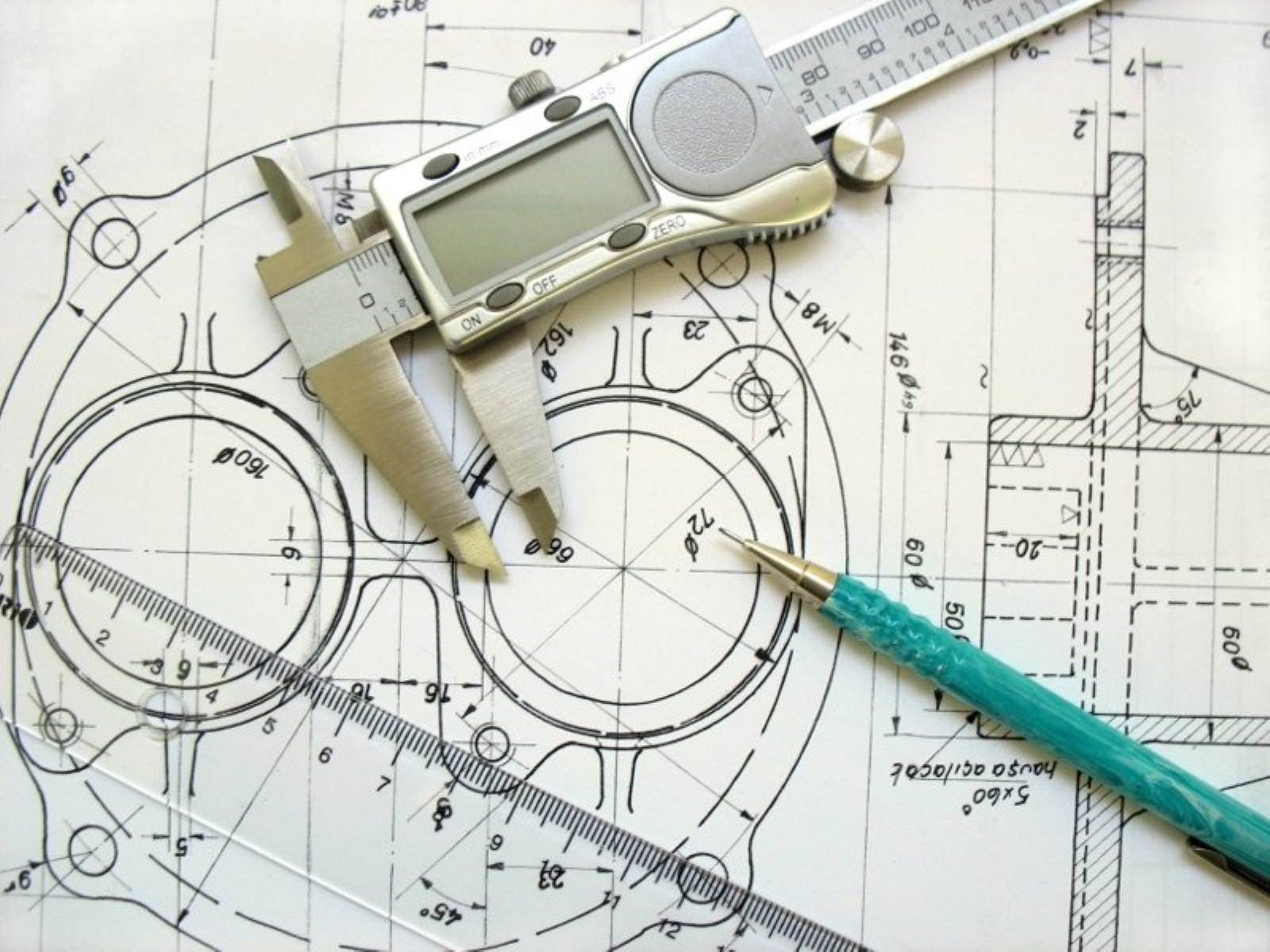
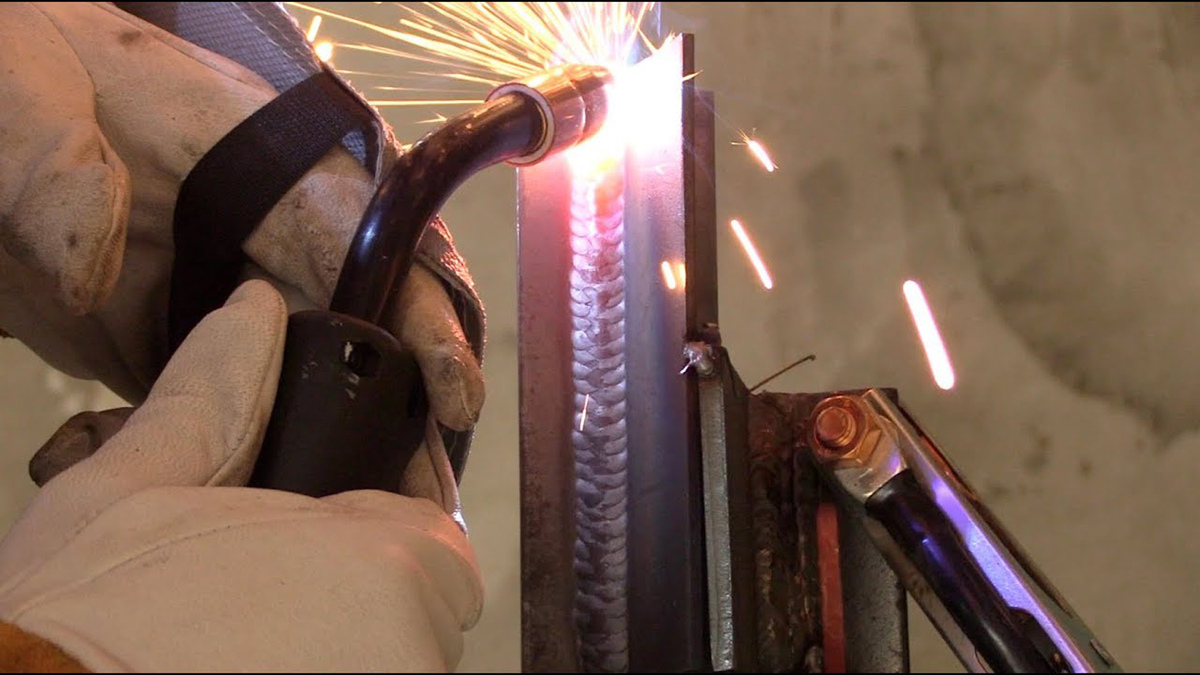
Reading a welding blueprint may seem daunting at first, with its multitude of symbols, dimensions, and specifications. However, with a little knowledge and practice, anyone can decipher these blueprints and gain valuable insight into the construction or fabrication project at hand.
Understanding welding blueprints is essential for welders, fabricators, and other professionals in the industry. These blueprints serve as a visual guide, providing essential information about the welding joints, welding positions, materials, dimensions, and tolerances required for a successful project.
In this article, we will explore the fundamentals of reading a welding blueprint, breaking down the various symbols, dimensions, and specifications commonly found. We will also discuss how to interpret welding notes, identify material types and thicknesses, and evaluate supplementary symbols.
By the end of this article, you will have a solid grasp of the key elements involved in reading a welding blueprint, allowing you to confidently analyze and execute welding projects with precision and accuracy.
Key Takeaways:
- Mastering the art of reading welding blueprints empowers professionals to gain valuable insights, ensure compliance with project requirements, and execute welds with precision and accuracy.
- Understanding welding blueprint symbols, dimensions, and specifications is crucial for interpreting and executing welding projects effectively, leading to the production of high-quality welds.
Read more: How To Read An Electrical Blueprint
Understanding Welding Blueprint Symbols
When reading a welding blueprint, it is crucial to have a clear understanding of the different symbols used. These symbols are used to represent various welding processes, joint types, weld profiles, and other important elements of the weld. Let’s explore some of the most common welding blueprint symbols:
- Welding Process Symbols: These symbols indicate the type of welding process to be used, such as stick welding, TIG welding, or MIG welding. Each process has its own unique symbol, allowing welders to identify the specific method required for the job.
- Joint Type Symbols: Joint type symbols represent the configuration of the welding joint. Common examples include butt joints, lap joints, and T-joints. Understanding these symbols helps determine how the two pieces of metal are to be joined together.
- Weld Profile Symbols: Weld profile symbols illustrate the desired shape of the weld bead. This includes symbols for fillet welds, groove welds, and other specific weld shapes. It is important to accurately interpret these symbols to achieve the desired weld profile.
- Non-Destructive Testing (NDT) Symbols: NDT symbols indicate any required testing methods, such as X-ray, ultrasonic testing, or magnetic particle inspection. These symbols help ensure the quality and integrity of the weld.
By familiarizing yourself with these symbols, you will be able to decipher the blueprint more effectively, understanding the specific requirements and expectations for the welding process.
In addition to symbol recognition, it is important to familiarize yourself with the specific dimensions and tolerances indicated on the blueprint. This information provides crucial guidelines for achieving the desired quality of the weld. We will explore this aspect further in the next section.
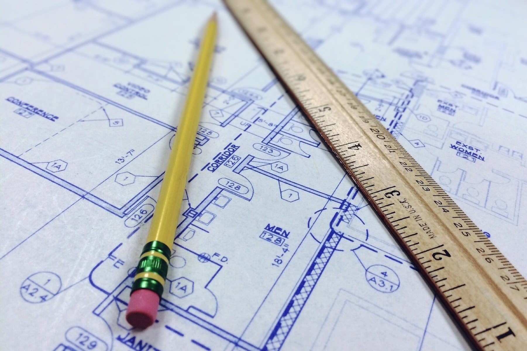
Interpreting Dimensions and Tolerances
Dimensions and tolerances play a critical role in welding blueprints, as they provide precise measurements and allowances for the weld. Understanding and interpreting these dimensions and tolerances is crucial for achieving accurate and high-quality welds. Let’s delve into the key aspects of interpreting dimensions and tolerances:
- Weld Length or Size: The dimensions specified on the blueprint indicate the length or size of the weld. These dimensions are typically indicated with a symbol and a numerical value, specifying the length in units such as inches or millimeters. It is essential to follow these dimensions closely to ensure the weld meets the required specifications.
- Tolerances: Tolerances indicate the permissible variations or deviations in a dimension. They define the acceptable range of measurements within which the weld must fall. Tolerances are usually represented as a plus or minus symbol followed by a numerical value. It is important to understand and adhere to these tolerances to ensure the weld is within the acceptable range.
- Fillet Weld Sizes: Fillet welds are commonly used in welding applications. The size of a fillet weld is usually specified on the blueprint. The size is indicated by the leg length or throat thickness of the weld. Leg lengths are typically specified in units such as inches or millimeters. With fillet welds, it is crucial to achieve the specified size to maintain the structural integrity of the joint.
- Gap Dimensions: Gap dimensions specify the allowable gap between two pieces of metal to be joined. These dimensions ensure proper fit-up and alignment between the two parts. Following the specified gap dimensions helps ensure a strong and secure weld joint.
Interpreting dimensions and tolerances accurately is essential for achieving the desired welding results. Failure to adhere to the specified dimensions and tolerances can result in weak welds, compromised structural integrity, or even welding defects. Therefore, it is crucial to carefully analyze and understand these aspects of the blueprint before commencing the welding process.
In the next section, we will explore the importance of identifying different weld types and positions on a welding blueprint.
Identifying Weld Types and Positions
Identifying the different weld types and positions is crucial when reading a welding blueprint. This information provides valuable insight into how the welds should be executed and the specific requirements for each weld. Let’s dive into the key aspects of identifying weld types and positions:
- Weld Types: Weld types refer to the specific methods of joining two pieces of metal together. Common weld types include fillet welds, groove welds, plug welds, and spot welds. Each weld type has its own unique characteristics and requirements. The blueprint will indicate the specific weld type to be used for each joint, allowing the welder to understand how to approach the welding process.
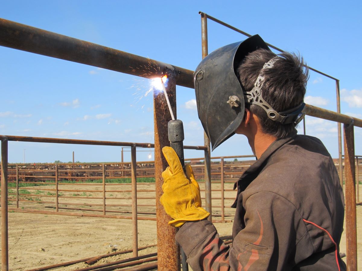
- Weld Positions: Weld positions refer to the orientation of the weld joint relative to the ground or horizontal reference plane. Common weld positions include flat, horizontal, vertical, and overhead positions. Understanding the specified weld position is important as it determines the technique, equipment setup, and welder’s body position during the welding process.
- Symbolic Representation: Weld types and positions are often represented by specific symbols on the welding blueprint. These symbols provide a clear visual representation of the required weld type and position for each joint. It is essential to be familiar with these symbols to accurately interpret and execute the welding process.
By being able to identify and understand the weld types and positions indicated on the blueprint, welders can ensure that the correct welding techniques are applied for each joint. This knowledge plays a significant role in achieving strong, durable, and visually appealing welds.
In the following section, we will discuss how to read weld symbols and understand the arrow side on a welding blueprint.
Reading Weld Symbols and Arrow Side
Weld symbols and the arrow side play a crucial role in understanding the specific requirements and details of a welding joint. They provide essential information regarding weld length, size, location, and other specifics that are vital for a successful welding process. Let’s explore how to effectively read weld symbols and understand the arrow side:
- Basic Weld Symbol Components: A weld symbol consists of several components, including the reference line, arrow, weld symbol, and supplementary symbols. The reference line represents the joint to be welded, while the arrow indicates the location and extent of the weld. The weld symbol provides additional information about the type, size, and other characteristics of the weld. Supplementary symbols may be used to provide further instructions or specifications.
- Arrow Side: The arrow side is the side of the joint that the arrow is pointing to. It indicates the side of the joint where the weld is to be applied. The arrow side is essential for determining the orientation and direction of the weld and ensures that the weld is applied correctly to achieve the desired joint quality and strength.
- Placement of Symbols: Weld symbols and the arrow side are typically located on the reference line or around the joint area on the welding blueprint. The symbols are positioned appropriately to indicate the specific requirements for each joint. It is important to accurately interpret the placement of these symbols to ensure proper execution and alignment of the weld.
Understanding how to read weld symbols and determine the arrow side is crucial for following the welding instructions accurately. Failure to interpret these symbols correctly can lead to improper weld placement, incorrect weld size, or other welding defects.
In the next section, we will discuss how to analyze specifications and welding notes provided on a welding blueprint.
When reading a welding blueprint, pay close attention to the welding symbols, dimensions, and material specifications to ensure accurate and precise welding.
Read more: How To Read Construction Blueprints
Analyzing Specifications and Welding Notes
Specifications and welding notes are essential components of a welding blueprint as they provide specific details and instructions for the welding process. Analyzing these specifications and notes is crucial for understanding the project requirements and ensuring the successful execution of the weld. Let’s delve into the key aspects of analyzing specifications and welding notes:
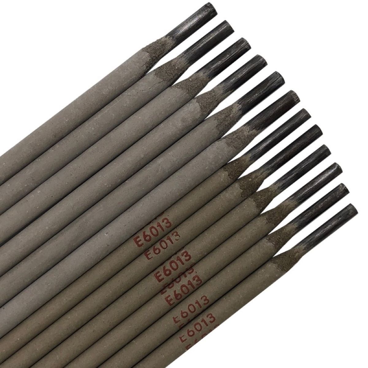
- Material Specifications: Specifications may include information about the type of material to be welded, such as steel, aluminum, or stainless steel. It may also specify the grade or composition of the material. Understanding the material specifications is critical as different materials require specific welding techniques, equipment, and consumables to achieve a quality weld.
- Welding Parameters: Specifications often provide information about the welding parameters, such as the welding process, current or voltage settings, travel speed, and electrode or filler wire type. These parameters play a significant role in achieving the desired weld quality and should be followed precisely to ensure a successful outcome.
- Welding Notes: Welding notes provide additional instructions or clarifications for specific welds or joints. These notes may include information about pre-weld or post-weld treatments, special considerations for particular joint configurations, or specific techniques to be employed. Paying careful attention to these notes helps ensure that all requirements and instructions are followed accurately.
Analyzing the specifications and welding notes on a blueprint allows welders to gain a comprehensive understanding of the project requirements and execute the welds accordingly. It ensures that the right materials, parameters, and techniques are utilized to achieve the desired weld quality and meet all project specifications.
In the next section, we will examine the importance of clarifying welding joint information when reading a welding blueprint.
Clarifying Welding Joint Information
Clarifying welding joint information is vital when reading a welding blueprint, as it provides a clear understanding of the joint configurations and requirements. Properly interpreting and visualizing the welding joint information is crucial for executing the welding process accurately. Let’s explore the importance of clarifying welding joint information:
- Joint Configuration: The welding joint information provides details about the joint configuration, such as whether it is a butt joint, lap joint, corner joint, or T-joint. Understanding the joint configuration is essential as it determines the welding techniques and preparations required for achieving a sound and strong weld.
- Joint Design: The joint design information specifies the specific geometry of the joint, including the depth of penetration, reinforcement, and bevel angle, if applicable. Accurately clarifying the joint design helps ensure proper fit-up and alignment, resulting in a successful welding process.
- Welding Position: The welding joint information also indicates the welding position, which refers to the orientation of the joint relative to gravity. Properly understanding the welding position allows the welder to adjust their technique and equipment setup accordingly, ensuring that the weld is performed with the appropriate settings and procedures.
By clarifying the welding joint information, welders can accurately visualize the requirements of each joint, enabling them to plan and execute the welding process effectively. It ensures that the welding techniques, equipment, and approaches utilized are suitable for the specific joint, resulting in high-quality, structurally sound welds.
In the following section, we will discuss the significance of recognizing material types and thicknesses when reading a welding blueprint.
Recognizing Material Types and Thicknesses
Recognizing material types and thicknesses is crucial when reading a welding blueprint, as it provides valuable information about the metals being joined and helps determine the appropriate welding techniques and settings. Understanding the material types and thicknesses helps ensure the successful execution of the welding process. Let’s explore the significance of recognizing material types and thicknesses:
- Material Types: The blueprint will indicate the type of material to be welded, such as steel, aluminum, stainless steel, or other alloys. Each material type has its own unique properties and welding characteristics, which necessitate specific techniques and considerations. Familiarizing yourself with the material types allows you to choose the appropriate welding method, consumables, and equipment for achieving a strong and reliable weld.
- Material Thicknesses: The blueprint will also specify the thicknesses of the materials being joined. Recognizing the material thickness is essential as it influences the welding parameters, such as current or voltage settings, travel speed, and joint preparation. Welding thicker materials may require higher heat input and slower travel speeds, while welding thinner materials may require lower heat input and faster travel speeds. Understanding the material thicknesses ensures that the welding process is optimized for the specific materials involved.
- Material Compatibility: Recognizing the material types also helps ensure compatibility between the base metal and the filler material. Different material combinations may have different welding requirements and considerations. It is important to select the appropriate filler material that is compatible with the base metal to achieve a strong metallurgical bond and prevent issues such as cracking or brittleness.
By accurately recognizing material types and thicknesses, welders can make informed decisions about welding procedures, equipment, and filler materials. This knowledge enables them to execute the welding process effectively, ensuring a high-quality weld that meets the structural and performance requirements of the project.
In the next section, we will discuss the significance of evaluating supplementary symbols on a welding blueprint.
Evaluating Supplementary Symbols
Supplementary symbols play a crucial role in providing additional information and instructions on a welding blueprint. These symbols complement the primary weld symbols and specifications, providing further clarity and guidance for the welding process. It is important to evaluate and understand the supplementary symbols to ensure accurate interpretation and execution of the weld. Let’s explore the significance of evaluating supplementary symbols:
- Positioning and Orientation: Supplementary symbols may indicate specific positioning or orientation requirements for the weld. For instance, a symbol may indicate that the weld needs to be performed with the workpiece in a certain position, such as vertical or overhead. This information guides the welder in adjusting their technique and equipment setup accordingly.
- Welding Sequence: Some welding projects require a specific welding sequence to ensure proper joint integrity and avoid distortion. Supplementary symbols may provide instructions regarding the order in which welds should be performed. Adhering to the specified welding sequence is crucial for maintaining the structural integrity of the weld and achieving the desired outcome.
- Special Preparations or Techniques: Supplementary symbols may also inform the welder of any special preparations or techniques required for a particular weld. This could include preheating the material, utilizing a specific gas shielding technique, or employing a particular welding process variant. Following these instructions ensures that the weld is performed correctly and meets the necessary criteria and standards.
Evaluating and understanding the supplementary symbols on a welding blueprint enhances the overall comprehension of the welding requirements. It allows the welder to address specific considerations and factors that may affect the weld quality and integrity. By paying attention to the supplementary symbols, welders can execute the welding process with precision and accuracy.
Now that we have examined the various elements involved in reading a welding blueprint, let’s conclude our article.
Read more: How To Read HVAC Blueprints
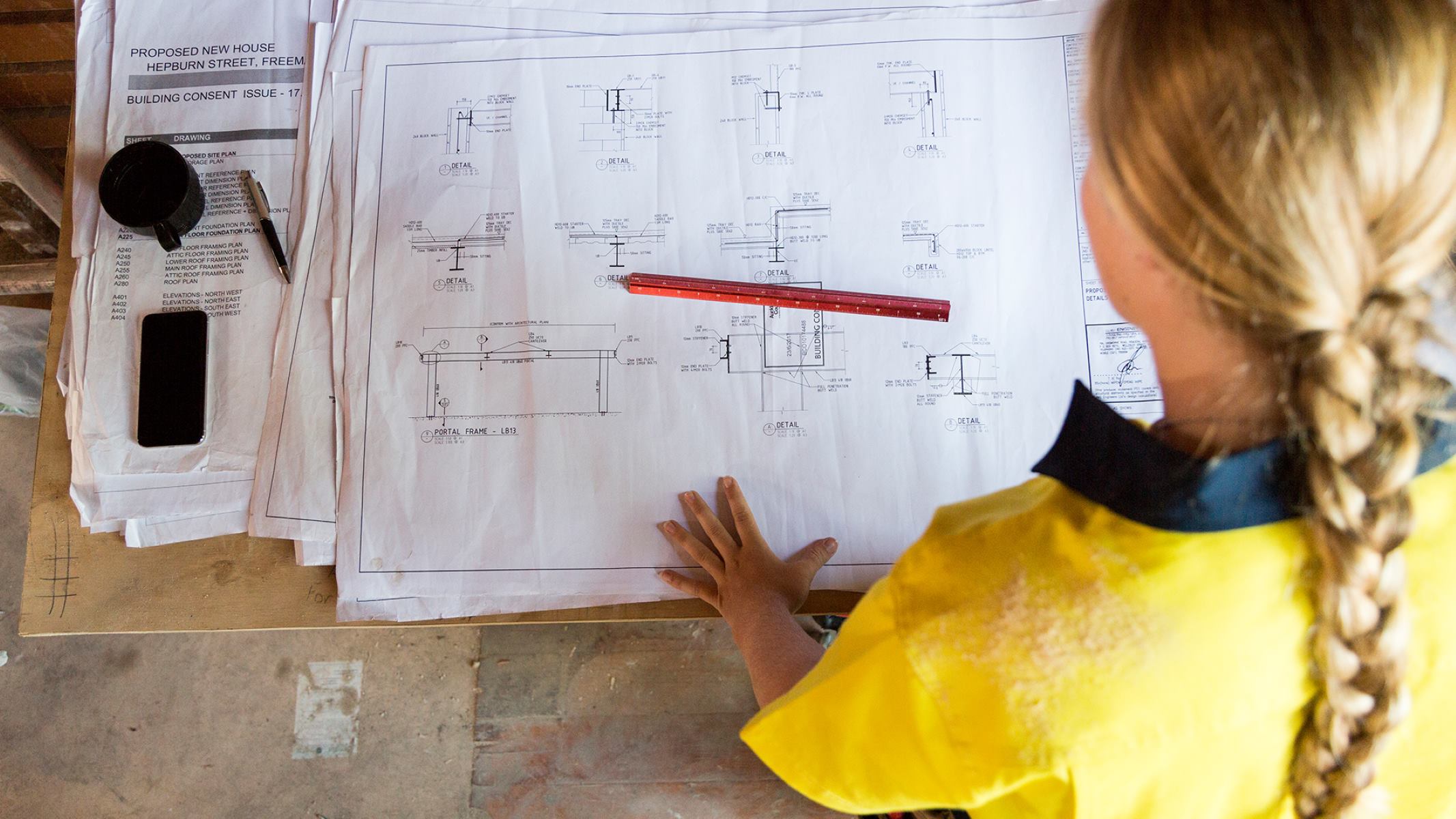
Conclusion
Reading a welding blueprint may initially seem complex and daunting, but with a solid understanding of the symbols, dimensions, specifications, and other important elements, anyone can interpret and decipher these blueprints effectively. By mastering the art of reading welding blueprints, welders, fabricators, and professionals in the industry can gain valuable insights into the welding process, ensure compliance with project requirements, and execute welds with precision and accuracy.
We explored the importance of understanding welding blueprint symbols, such as welding process symbols, joint type symbols, weld profile symbols, and non-destructive testing symbols. Recognizing these symbols is crucial for identifying the welding process, joint configuration, and desired weld profile.
We also discussed the significance of interpreting dimensions and tolerances on a welding blueprint. Dimensions provide precise measurements, while tolerances define the allowable variations. Understanding these aspects ensures that welds meet the required specifications.
Identifying weld types and positions allows welders to execute appropriate techniques and equipment setups, ensuring that welds are applied correctly. Reading weld symbols and understanding the arrow side provides valuable information about the location and extent of the weld, enabling accurate execution of the welding process.
Analyzing specifications and welding notes is essential for comprehending project requirements and following specific instructions. By understanding material types and thicknesses, welders can select appropriate welding techniques, consumables, and equipment for achieving desired weld quality. Evaluating supplementary symbols provides additional guidance on positioning, orientation, welding sequences, and special preparations or techniques that may be required.
By mastering the skills of reading a welding blueprint, professionals in the industry can enhance their ability to analyze, interpret, and execute welding projects with precision and efficiency. This leads to the production of high-quality welds, ensuring the structural integrity, durability, and performance of the final product.
So, the next time you come across a welding blueprint, approach it with confidence and utilize the knowledge gained from this article to understand the symbols, dimensions, specifications, and instructions. With practice, reading welding blueprints will become second nature, empowering you to excel in your welding endeavors.
Frequently Asked Questions about How To Read A Welding Blueprint
Was this page helpful?
At Storables.com, we guarantee accurate and reliable information. Our content, validated by Expert Board Contributors, is crafted following stringent Editorial Policies. We're committed to providing you with well-researched, expert-backed insights for all your informational needs.


0 thoughts on “How To Read A Welding Blueprint”