Home>diy>Architecture & Design>How Do I Read A Blueprint

Architecture & Design
How Do I Read A Blueprint
Modified: January 6, 2024
Learn how to read a blueprint in architecture design. Gain a deeper understanding of the symbols, measurements, and plans used in construction projects.
(Many of the links in this article redirect to a specific reviewed product. Your purchase of these products through affiliate links helps to generate commission for Storables.com, at no extra cost. Learn more)
Introduction
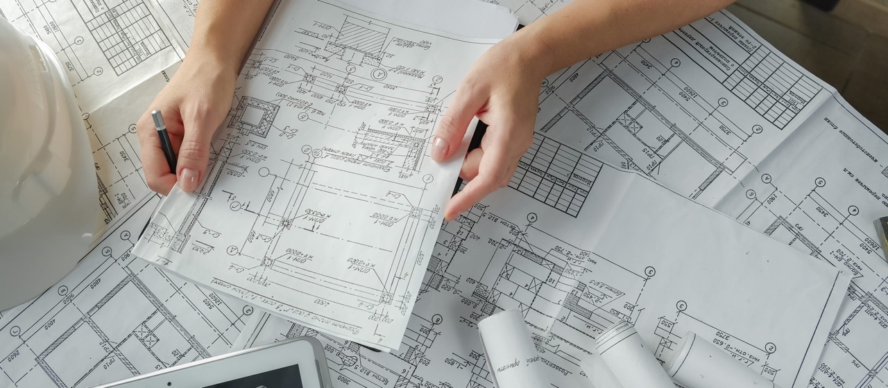
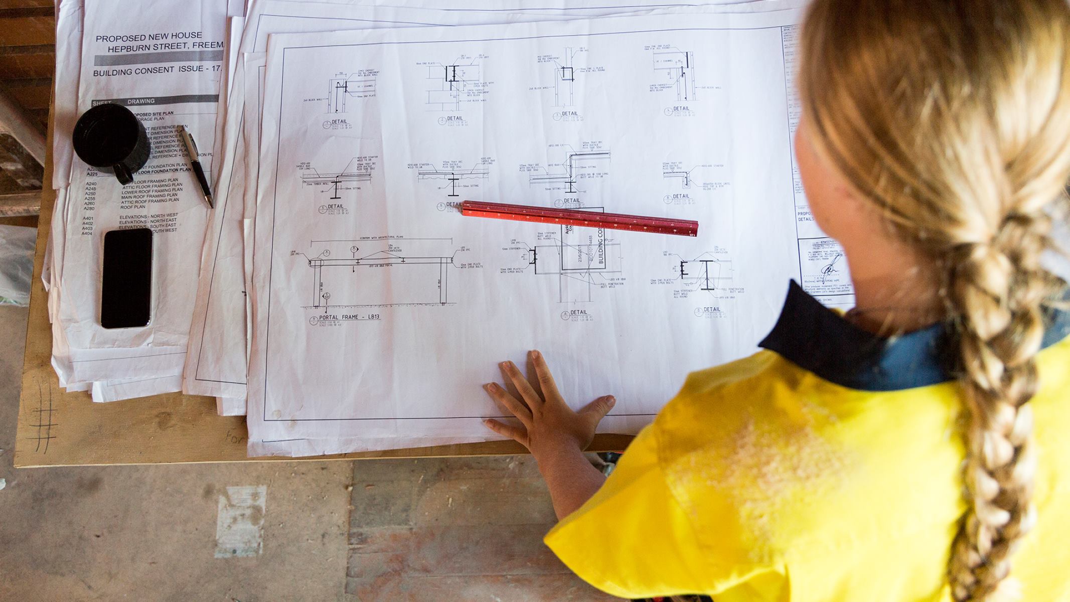
When it comes to understanding the design and construction of a building, reading a blueprint is an essential skill for architects, engineers, contractors, and anyone involved in the construction industry. Blueprints, also known as architectural plans or drawings, are detailed representations of a building’s design, showcasing its layout, dimensions, materials, and various other specifications.
While blueprints may appear intimidating to the untrained eye, learning how to read them can provide valuable insights into the intricacies of a building’s architecture and help you navigate its construction process. In this article, we will delve into the fundamentals of reading blueprints, covering the basic symbols, terms, dimensions, and other key elements that make up these technical drawings.
By the end of this article, you’ll have a solid foundation in blueprint reading, enabling you to decipher the wealth of information presented in these essential documents. So, let’s begin our journey into the fascinating world of blueprint reading!
Key Takeaways:
- Mastering blueprint reading is crucial for architects, engineers, and contractors to accurately interpret design intentions, ensure compliance, and contribute to the creation of safe and visually appealing structures.
- Understanding scales, symbols, dimensions, and annotations on blueprints is essential for accurate comprehension of a building’s design, enabling effective coordination and successful implementation of design intent.
Read more: How To Read An Electrical Blueprint
Understanding the Basic Symbols and Terms
Before diving into the intricacies of reading a blueprint, it’s important to familiarize yourself with the basic symbols and terms commonly used in architectural drawings. These symbols and terms serve as a universal language that architects and construction professionals use to communicate their design intentions.
One of the first things you’ll encounter on a blueprint is the legend or key, which explains the meaning of all the symbols used throughout the drawing. Symbols can represent various elements such as doors, windows, walls, electrical fixtures, plumbing fixtures, and more. Familiarizing yourself with these symbols will help you quickly identify different features and components of the building.
In addition to symbols, blueprints also include various terms and abbreviations. These terms are used to describe different elements of the building or specify certain actions or requirements. For example, “RCP” stands for “Reflected Ceiling Plan,” which depicts the ceiling layout from a top-down perspective. “SFT” represents “Square Feet” and is used to denote the area measurement of a space. Understanding these terms will allow you to accurately interpret the information provided on the blueprint.
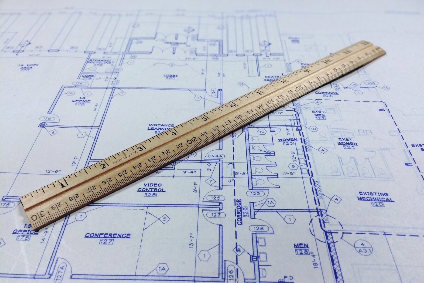
Another important aspect to consider when reading blueprints is the scale. Blueprints are typically drawn to scale, which means that a certain ratio is used to represent the actual dimensions of the building. Common scales include 1/4 inch = 1 foot or 1/8 inch = 1 foot. The scale is usually indicated on the drawing, and it helps you understand the relative size and proportions of different elements in the building.
As you delve deeper into blueprint reading, you’ll also encounter different types of lines. These lines have specific meanings and help convey important information about the design and construction of the building. For example, solid lines often indicate walls or major structural elements, while dashed lines may represent hidden features or objects.
By familiarizing yourself with the basic symbols and terms commonly used in blueprints, you’ll be well-equipped to navigate the complex visual language of architectural drawings. This understanding will serve as a solid foundation for interpreting and analyzing the various components of a blueprint.
Interpreting the Scale
One of the essential elements in reading a blueprint is understanding the scale. The scale is a critical component that allows you to interpret the dimensions and measurements on the drawing accurately. It represents the ratio of the size of an object on the blueprint to its actual size in real life.
Typically, the scale is expressed as a fraction, such as 1/4 inch = 1 foot or 1/8 inch = 1 foot. This means that every 1/4 inch or 1/8 inch on the blueprint represents 1 foot in reality. It’s important to note that the scale may vary depending on the complexity and size of the building. Always verify the scale indicated on the blueprint before interpreting any measurements.
The scale is typically presented in a scale bar or a graphic representation at a specific location on the blueprint. The scale bar consists of a line divided into equal segments, with each segment representing a specific measurement. It helps you quickly and accurately estimate the size of different elements and spaces in the building.
When reading a blueprint, the scale allows you to determine the length, width, and height of various elements. For example, if a wall on the blueprint measures 4 inches, you can multiply this measurement by the scale factor to determine the actual length of the wall in feet. If the scale is 1/4 inch = 1 foot, the actual length of the wall would be 16 feet.
It’s important to keep in mind that the scale affects all dimensions on the blueprint, including walls, windows, doors, and other features. By understanding the scale, you can accurately visualize the size and proportions of different elements in the building.
In addition to measuring dimensions, the scale also helps you understand the layout and spatial relationships between different elements. By evaluating the scale, you can determine the distance between walls, the placement of doors and windows, and the overall flow of the space.
Interpreting the scale correctly is crucial to ensure that you comprehend the dimensions and proportions accurately. Take the time to study the scale bar and understand how it relates to the actual dimensions. With this understanding, you’ll be able to navigate the blueprint more effectively and visualize the building as it will appear in reality.
Identifying Different Types of Lines
When reading a blueprint, understanding the different types of lines used is essential. Lines are used to convey various information about the design and construction of the building, such as boundaries, dimensions, hidden features, and more. Different types of lines are represented by specific styles and patterns.
One of the most common types of lines found on blueprints is the solid line. Solid lines are typically used to represent visible or physical elements of the building. For example, solid lines may indicate the outline of walls, doors, windows, and other structural components. These lines help you identify the boundaries and dimensions of different spaces within the building.
Dashed lines, on the other hand, are used to represent hidden or obscured features of the building. They are often used to depict items that are located behind walls or hidden from view, such as pipes, electrical wiring, or ductwork. Dashed lines provide insights into the internal structure and layout of the building, allowing you to understand how the various systems are integrated.
Another type of line commonly found on blueprints is the dotted line. Dotted lines are typically used to indicate objects or features that are not yet constructed, such as future extensions or additions. They also signify elements that are temporary or removable, such as furniture, equipment, or partitions.
Arrows and leaders are additional line types that are used to provide annotations and references on the blueprint. Arrows are often used to indicate the direction of a specific component or the flow of a system, such as the direction of a door swing or the direction of water flow in a plumbing system. Leaders, on the other hand, are lines with an arrow or dot at one end, used to point to a specific object or provide additional information or dimensions.
Understanding the different types of lines and their meanings is crucial for accurately interpreting a blueprint. By recognizing solid lines, you can identify the boundaries and dimensions of various elements in the building. Dashed lines give you insights into hidden or obscured features. Dotted lines indicate future or temporary elements. And arrows and leaders provide additional guidance and annotations.
By having a clear understanding of these different line types, you’ll be well-equipped to navigate the blueprint and gain a comprehensive understanding of the design and construction of the building.
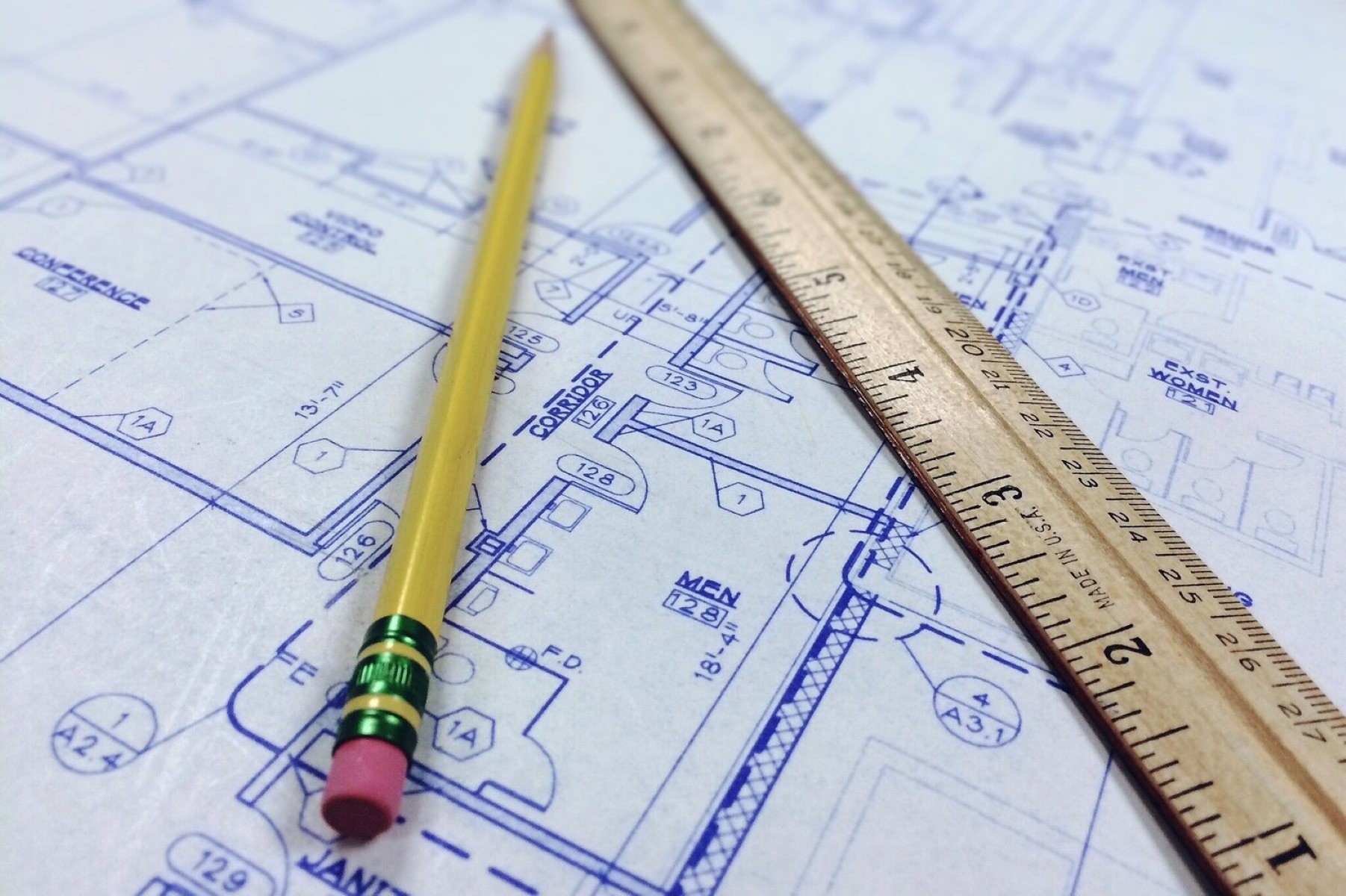
Reading Dimensions and Measurements
Dimensions and measurements play a vital role in understanding the size and layout of a building. When reading a blueprint, it’s essential to accurately interpret the dimensions provided to ensure precise construction and proper alignment of various components.
Dimensions on a blueprint are typically indicated by numbers or symbols and are accompanied by lines or arrows to show the extent or length of an object. It’s important to pay attention to the units of measurement used, whether it’s in inches, feet, or meters. Understanding the units will help you calculate and visualize the actual size of different elements in the building.
The dimensions on a blueprint can refer to various aspects, such as length, width, height, and depth. For example, a dimension might indicate the length of a wall or the width of a door opening. By referring to these measurements, you can accurately determine the size and proportions of different architectural features.
In addition to linear dimensions, blueprints often include angular dimensions to specify angles and slopes. These measurements are crucial for ensuring that structures are built correctly and to the necessary specifications. For example, a blueprint might include the angle of a roof pitch or the slope of a ramp.
When interpreting dimensions, it’s important to consider the scale used on the blueprint. As mentioned earlier, blueprints are typically drawn to scale, and the dimensions are proportionate to the actual size of the building. By referencing the scale, you can accurately calculate the real-world measurements from the dimensions provided on the blueprint.
To assist in reading dimensions, blueprints often include callouts or symbols that provide additional information. Callouts are annotations that specify particular dimensions or features, often accompanied by notes or arrows to clarify their location. Symbols, such as circles or triangles, may be used to represent certain measurements or components.
By carefully examining the dimensions and measurements on a blueprint, you’ll be able to determine the size, proportions, and relationships between various elements of the building. This information is crucial for ensuring accurate construction and precise alignment, resulting in a well-designed and functional structure.
Read more: How To Read A Welding Blueprint
Understanding Architectural Symbols and Notations
Architectural symbols and notations are graphical elements used in blueprints to represent various features, components, materials, and construction techniques. These symbols serve as a visual shorthand, allowing architects, engineers, and construction professionals to communicate specific design details succinctly.
Architectural symbols can represent a wide range of elements, including doors, windows, fixtures, electrical outlets, plumbing pipes, and structural components. Each symbol is carefully designed to convey the intended meaning and characteristics of the represented item. By understanding these symbols, you can quickly identify and interpret different aspects of the building’s design.
Notations, on the other hand, are used to provide additional information and clarifications on the blueprint. These can include text, abbreviations, or numbers that provide specific instructions or outline requirements. Notations help ensure that all parties involved in the construction process have a clear understanding of the design intent and necessary actions.
One common architectural symbol is the door symbol, which represents the location and swing direction of doors. The symbol typically includes a curved line to indicate the swing direction, and accompanying measurements may specify the width and height of the door. Similarly, window symbols indicate the size and type of windows, with various shapes and sizes representing different window styles.
Electrical symbols are essential for understanding the location and type of electrical fixtures and components. These symbols can represent outlets, switches, light fixtures, and other electrical elements. By referencing these symbols, electricians can accurately install electrical systems according to the design specifications.
Plumbing symbols are used to indicate the location and specifications of plumbing fixtures, pipes, and fittings. These symbols represent elements such as sinks, toilets, showers, and water supply lines. By understanding these symbols, plumbers can ensure proper installation and alignment of plumbing systems.
Structural symbols are crucial for understanding the structural components and load-bearing elements of a building. Symbols may represent columns, beams, trusses, and other structural elements. These symbols help engineers and builders ensure the structural integrity of the building and adhere to safety regulations.
By familiarizing yourself with architectural symbols and notations, you can effectively navigate a blueprint and decode the design intentions. Understanding these symbols and notations is essential for accurately interpreting the blueprint and ensuring that construction aligns with the architect’s vision.
Identifying Key Features and Sections
When reading a blueprint, identifying key features and sections is crucial for understanding the layout and functionality of a building. These features and sections provide valuable insights into the different spaces and components that make up the structure.
One of the first key features to identify on a blueprint is the building’s footprint. The footprint represents the outline of the building on the ground and gives you a sense of its overall shape and size. By examining the footprint, you can understand the general layout and orientation of the building.
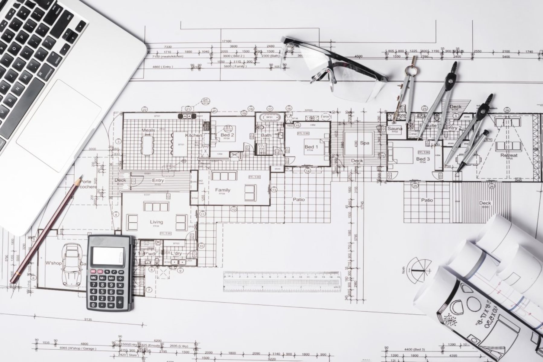
Another important aspect to look for is the floor plan. The floor plan provides a detailed representation of each level of the building, showing the arrangement of rooms, walls, doors, and other essential features. By studying the floor plan, you can identify the different functional areas, such as living spaces, bedrooms, kitchens, bathrooms, and more.
In addition to the floor plan, blueprints often include sections and elevations. Sections are vertical slices through the building, showing a cross-sectional view of the interior. These sections help you visualize the height and depth of various spaces, as well as the relationships between different levels. Elevations, on the other hand, are flat, two-dimensional views of the exterior of the building from different angles. They show the façade of the building, allowing you to identify architectural details, materials, and overall aesthetics.
As you navigate the blueprint, it’s important to pay attention to key features such as stairs, elevators, and corridors. These elements help you understand the circulation and flow of movement within the building, ensuring efficient accessibility and functionality.
Identifying important components such as mechanical rooms, utility areas, and storage spaces is crucial for understanding the building’s infrastructure. These rooms house essential equipment and systems, including HVAC (heating, ventilation, and air conditioning), electrical panels, water heaters, and more.
Additionally, keep an eye out for special features or amenities that may be highlighted on the blueprint. This could include fireplaces, outdoor spaces, balconies, or other distinctive elements that enhance the functionality or appeal of the building.
By identifying key features and sections on a blueprint, you can gain a comprehensive understanding of the building’s layout, functionality, and architectural details. This knowledge is vital for architects, engineers, contractors, and anyone involved in the construction process to ensure accurate and successful implementation of the design.
Reading Notes and Annotations
Notes and annotations are important elements found on blueprints that provide additional information, instructions, and clarifications about specific design or construction details. These annotations can help ensure that all parties involved in the building process understand the intended design intent and follow specific guidelines.
Notes are typically written in plain language and are used to communicate specific instructions or requirements. They may provide details on materials to be used, construction techniques to be followed, or any other specific guidelines that need to be followed during the construction process. Examples of notes may include instructions on the type of flooring to be installed or the specific paint color to be used on certain surfaces.
Annotations, on the other hand, are graphical elements accompanied by text or symbols that provide additional information or highlight important elements on the blueprint. Annotations can include arrows, circles, or callouts that draw attention to specific features or dimensions. They may also point out areas of concern or components that require special attention.
Reading and understanding notes and annotations is crucial for accurately interpreting the blueprint and ensuring that the design intent is carried out during construction. It is important to pay close attention to the placement and context of the notes and annotations to fully comprehend their meaning.
Annotations can also be used to indicate changes or revisions that have been made to the original blueprint. These revisions are often denoted with cloud shapes or revision clouds, with accompanying text to explain the change. It’s essential to carefully review these annotations to ensure that you are working with the most up-to-date version of the blueprint.
In addition to providing instructions and clarifications, notes and annotations can also include important safety information. These may include warnings about potential hazards, requirements for safety equipment, or emergency exit locations. It is crucial for all parties involved in the construction process to carefully review and understand these safety-related notes to ensure a safe working environment.
By thoroughly reading and understanding the notes and annotations on a blueprint, you can ensure that you have a comprehensive understanding of the design intent, specific requirements, and any important safety considerations. These annotations serve as a valuable source of information and guidance throughout the construction process, helping to prevent errors and ensure successful implementation of the blueprint’s design.
When reading a blueprint, start by familiarizing yourself with the title block to understand the scale, date, and other important information about the drawing. This will help you interpret the dimensions and details accurately.
Analyzing Sections and Elevations
Sections and elevations are crucial elements of a blueprint that provide valuable insights into the vertical dimensions, structural details, and aesthetic aspects of a building. Analyzing these sections and elevations is essential for understanding how different levels and features of the building interact and align.
Sections are vertical cuts through the building that provide a detailed cross-sectional view. These sections allow you to visualize the interior spaces and understand the relationships and dimensions between different levels of the building. By studying sections, you can identify the height and depth of rooms, the placement of structural elements, and the flow of circulation within the building.
Elevations, on the other hand, provide a two-dimensional view of the exterior of the building. Elevations showcase the façade of the building, allowing you to grasp the architectural style, proportions, and material choices. By examining elevations, you can identify key design elements such as windows, doors, rooflines, and decorative features that contribute to the building’s overall aesthetic appeal.
When analyzing sections and elevations, it’s important to pay attention to the scale and dimensions presented. Measurements provided on sections and elevations allow you to understand the heights of ceilings, the thickness of walls, the clearance between floors, and the overall proportions of the building. By carefully evaluating these measurements, you can ensure accurate construction and proper alignment of different elements.
Sections and elevations also provide insights into the structural components of the building. By examining sections, you can identify the placement of columns, beams, and other load-bearing elements, gaining an understanding of how the building supports its weight. Elevations may depict the arrangement of external structural elements such as balconies, canopies, or support structures.
Furthermore, sections and elevations allow you to assess the integration of various building systems. Sections may indicate the location of HVAC ducts, electrical wiring, plumbing pipes, or fire protection systems. Elevations may showcase the placement of mechanical equipment, such as air conditioning units or exhaust vents. These details are essential for coordinating the installation of systems effectively.
By closely analyzing sections and elevations, you can gain a comprehensive understanding of the building’s vertical dimensions, structural details, and aesthetic elements. This knowledge is crucial for architects, engineers, and construction professionals to ensure accurate implementation of the design and construction of the building.
Read more: How To Read Construction Blueprints
Identifying Materials and Finishes
Identifying materials and finishes is a crucial aspect of reading a blueprint as it provides insight into the aesthetic and functional aspects of a building. Understanding the materials and finishes specified on the blueprint ensures accurate construction and helps achieve the desired design intent.
Blueprints often include notations and symbols that represent different materials and finishes. These notations may specify the type of material, such as wood, concrete, steel, or glass, and indicate the location or extent of its use. For example, a symbol may denote that a certain wall is constructed with brick, while another symbol may indicate the use of metal panels for a specific facade element.
In addition to the type of material, blueprints may also provide information about the finish or surface treatment to be applied. This includes details on paint colors, texture variations, or coating options. It is important to pay attention to these details to accurately achieve the desired visual and tactile qualities of the finished building.
Identifying the specified materials is crucial for proper coordination during the construction process. It ensures that the correct materials are sourced and used, resulting in a structurally sound and aesthetically pleasing building. It also helps ensure compatibility between different building components and systems.
Understanding the specified finishes is equally important as it contributes to the overall design and ambiance of the building. Finishes can vary from smooth and polished surfaces to textured or patterned treatments, offering visual interest and tactile experiences. By correctly identifying and applying the specified finishes, the building can achieve the desired aesthetic qualities.
By closely examining the blueprint and its accompanying notes and symbols, you can accurately identify the materials and finishes specified for different elements of the building. This information is crucial for architects, contractors, and suppliers to ensure that the correct materials are sourced and used during the construction process. It helps maintain design integrity and ensures that the final result aligns with the envisioned aesthetic and functional attributes of the building.
Reviewing Electrical and Plumbing Plans
Reviewing electrical and plumbing plans is a critical step in understanding the infrastructure and functionality of a building. These plans outline the layout, placement, and specifications of electrical and plumbing systems, ensuring that they are installed correctly and meet the building’s requirements.
Electrical plans provide detailed information about the electrical wiring, outlets, fixtures, and systems of a building. These plans indicate the location and type of electrical panels, switches, and outlets throughout the space. By reviewing the electrical plan, you can understand the distribution of power, the circuitry, and the capacity of the electrical system.
It’s important to identify the location of electrical panels and understand their capacity to ensure that the electrical load is distributed properly and in compliance with safety standards. Electrical plans also provide information on the placement of lighting fixtures, which helps determine the lighting design and ambiance of the space.
Plumbing plans, on the other hand, detail the layout and specifications of the plumbing system within the building. These plans indicate the placement of pipes, fixtures, and drainage systems. By reviewing the plumbing plan, you can identify the location of sinks, toilets, showers, and other plumbing fixtures.
Understanding the plumbing plan is crucial for ensuring proper water supply and drainage throughout the building. It allows for effective coordination with other building systems, such as HVAC and fire protection, to prevent conflicts or interference.
Both electrical and plumbing plans include symbols and notations that represent specific elements. These symbols indicate the type and size of fixtures, the routing of pipes and conduits, and other important details. Familiarizing yourself with these symbols is essential for accurately interpreting the plans and coordinating with electricians and plumbers during the construction process.
Reviewing electrical and plumbing plans helps identify any potential conflicts or issues that may arise during construction. It ensures that the necessary infrastructure is in place to support the building’s functional requirements. Additionally, understanding these plans allows for efficient installation, inspection, and maintenance of electrical and plumbing systems.
By carefully reviewing electrical and plumbing plans, architects, engineers, contractors, and other professionals involved in the construction process can ensure that the building’s electrical and plumbing systems are integrated seamlessly, meeting safety standards and functional needs.
Recognizing HVAC Systems
Recognizing HVAC (Heating, Ventilation, and Air Conditioning) systems on a blueprint is crucial for understanding the indoor climate control and air quality management of a building. HVAC systems play a significant role in creating a comfortable and healthy environment for occupants, and identifying them on the blueprint ensures successful installation and operation.
HVAC plans provide detailed information about the layout, components, and specifications of the heating and cooling systems within the building. These plans indicate the location of HVAC units, ductwork, vents, and control panels. By reviewing the HVAC plan, you can gain insights into how the system will distribute conditioned air throughout the building.
The HVAC plan will typically include symbols and notations that represent different HVAC components and their specifications. These symbols may indicate the size and capacity of HVAC units, the routing of ductwork, and control mechanisms. Familiarizing yourself with these symbols is essential for accurately interpreting the plans and coordinating with HVAC contractors during the construction process.
Understanding the HVAC plan allows you to assess the thermal comfort and air quality within the building. The plan will indicate the locations of heating and cooling units, ensuring that they are strategically placed to provide optimal temperature control in various areas. It will also highlight the positions of air outlets and return vents, helping to ensure proper air circulation and ventilation throughout the building.
Additionally, the HVAC plan provides insights into energy efficiency measures and sustainability considerations. The plan may outline the use of energy-efficient equipment, such as high-efficiency HVAC units or heat recovery systems. By recognizing these elements, you can assess the building’s energy performance and identify opportunities for optimizing energy consumption and reducing environmental impact.
Reviewing the HVAC plan also allows for coordination with other building systems, such as electrical and plumbing. This coordination ensures proper integration and avoids conflicts or interference between different infrastructure components. It also allows for efficient installation, maintenance, and troubleshooting of the HVAC system.
By recognizing HVAC systems on a blueprint, architects, engineers, contractors, and other professionals involved in the construction process can ensure that the building will have an effective and efficient HVAC system in place. This contributes to the comfort, health, and overall functionality of the building, meeting the needs of its occupants.
Studying Structural Components
Studying the structural components on a blueprint is essential for understanding the stability, load-bearing capacity, and overall integrity of a building. The structural components serve as the backbone of the structure and ensure that it can withstand the forces and loads it will encounter over its lifespan.
The structural components on a blueprint include elements such as columns, beams, slabs, walls, and foundations. These components are carefully designed to support the weight of the building and distribute the loads to the ground. By studying these components, you can assess the structural system and its ability to resist forces such as gravity, wind, earthquakes, and other external factors.
When examining the structural components, it’s important to pay attention to the dimensions, placement, materials, and connections specified on the blueprint. These details provide insights into the design intent and structural requirements of the building. The dimensions indicate the size and proportions of the structural members, while the materials specified determine their strength and durability.
Key elements to focus on when studying the structural components include the placement of columns and beams, the span length of different members, and the connections between them. A well-designed structural system will efficiently transfer loads, minimize deflection, and ensure stability.
Understanding the structural components also allows for coordination with other building systems and elements. For example, studying the structural components helps determine the placement of utilities like plumbing and electrical systems, ensuring they align with the available space and do not compromise the integrity of the structure.
The structural components on a blueprint may be represented through symbols, notations, or detailed drawings. These specifications provide insight into the size, type, and positioning of the components. They may also include details about reinforcement, fire protection, or other specific requirements to meet building codes and regulations.
By studying the structural components on a blueprint, architects, engineers, contractors, and other professionals involved in the construction process can ensure that the building’s structural system is designed and built robustly. This understanding helps prevent structural failures, ensures safety, and provides longevity to the building.
Read more: How To Read HVAC Blueprints
Examining Door and Window Schedules
Examining door and window schedules on a blueprint is essential for understanding the type, size, and location of these important architectural elements. Door and window schedules provide a comprehensive overview of all the doors and windows in a building, ensuring accurate installation and optimal functionality.
A door schedule lists all the doors in the building, along with their specifications. This includes details such as the door type, dimensions, swing direction, material, and any additional features or hardware. By examining the door schedule, you can quickly identify the location of each door and understand its specific characteristics.
Understanding the door schedule is crucial for proper coordination with contractors and suppliers during the construction process. It ensures that the correct doors are sourced, delivered, and installed according to the design specifications. The door schedule also helps estimate costs and plan for any necessary adjustments or modifications.
Similarly, a window schedule provides important information about each window in the building. The schedule typically includes details such as the window type, dimensions, material, glazing, and any additional features or accessories. By reviewing the window schedule, you can easily identify the location and characteristics of each window.
The window schedule is essential for coordinating with suppliers and installers to ensure that the correct windows are ordered and installed. It allows for proper sizing, framing, and sealing of each window, ensuring energy efficiency, weather resistance, and acoustic performance. The schedule also facilitates cost estimation and ensures compliance with building codes and regulations.
In addition to the specifications, door and window schedules may include symbols or notations that provide additional information. These symbols represent specific features or instructions related to each door or window, such as the inclusion of hardware, security measures, or fire ratings.
Examining door and window schedules helps architects, contractors, and other professionals involved in the construction process understand the design intent, select appropriate doors and windows, and ensure that the building meets functional requirements and aesthetics. By carefully reviewing these schedules, the installation process can be streamlined, and the overall quality and performance of the doors and windows can be maintained.
Conclusion
In conclusion, the ability to read and interpret blueprints is a critical skill for architects, engineers, contractors, and anyone involved in the construction industry. Understanding the various symbols, terms, and notations allows for accurate comprehension of a building’s design and specifications. By delving into blueprints, we have explored the fundamental aspects of blueprint reading, including interpreting scales, identifying different types of lines, reading dimensions, and understanding architectural symbols.
We learned how to identify key features and sections on a blueprint, such as the building’s footprint, floor plans, sections, and elevations. These elements provide insights into the layout, functionality, and visual aspects of the building. By studying and analyzing them, we can gain a comprehensive understanding of the design intent and make informed decisions during the construction process.
Reviewing notes and annotations on blueprints is essential for fully understanding the design intent, specific requirements, and safety considerations. These notes and annotations provide additional guidance and instructions, ensuring accurate implementation of the building’s design and compliance with regulations.
Furthermore, understanding materials, finishes, and fixture schedules allows for effective coordination and ensures that the correct materials are sourced, installed, and used. By adhering to these specifications, the building can achieve the desired aesthetics, durability, and functionality.
Lastly, we explored how to recognize and analyze HVAC systems, plumbing plans, electrical plans, and structural components on blueprints. Understanding these systems and components is crucial for ensuring proper installation, functionality, and compliance with safety standards. It enables effective coordination among different disciplines and ensures the successful integration of various building systems.
In summary, the ability to read blueprints allows professionals in the construction industry to fully grasp the intricacies and nuances of a building’s design. It enables accurate interpretation, effective communication, and successful implementation of design intent. By mastering blueprint reading, professionals can contribute to the creation of safe, functional, and visually appealing structures.
Frequently Asked Questions about How Do I Read A Blueprint
Was this page helpful?
At Storables.com, we guarantee accurate and reliable information. Our content, validated by Expert Board Contributors, is crafted following stringent Editorial Policies. We're committed to providing you with well-researched, expert-backed insights for all your informational needs.


0 thoughts on “How Do I Read A Blueprint”