Home>diy>Architecture & Design>How Are Part Dimensions Found On A Blueprint?

Architecture & Design
How Are Part Dimensions Found On A Blueprint?
Modified: September 1, 2024
Discover how architects and designers determine part dimensions on blueprints. Gain insights into the process of architecture design and blueprint reading.
(Many of the links in this article redirect to a specific reviewed product. Your purchase of these products through affiliate links helps to generate commission for Storables.com, at no extra cost. Learn more)
Introduction
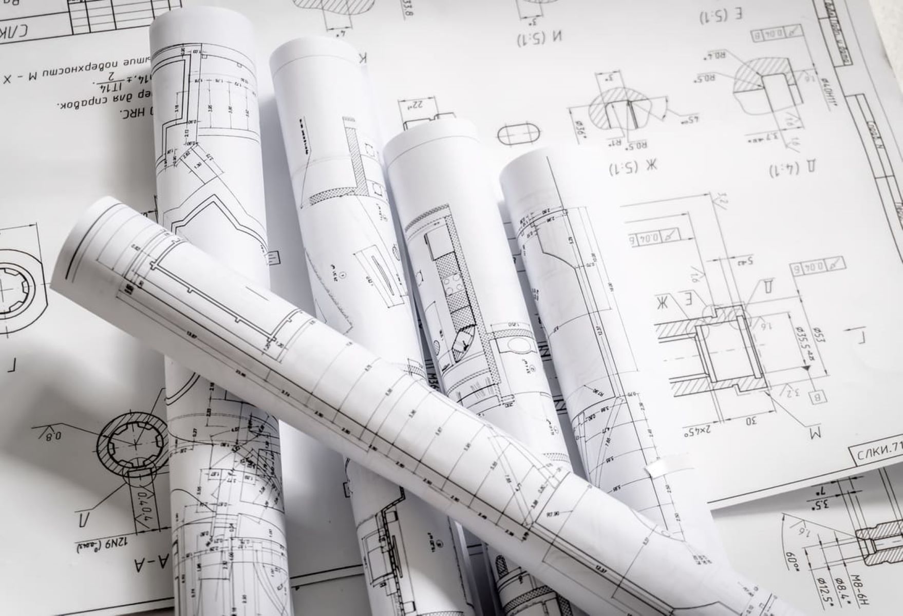
Blueprints are essential tools in architecture and engineering, providing detailed plans for construction projects. They contain a wealth of information, including part dimensions, that are vital for accurately building structures. Understanding how part dimensions are found on a blueprint is crucial for anyone involved in the construction industry.
In this article, we will explore the process of reading and interpreting part dimensions on blueprints. We will discuss the different types of dimensioning techniques used, as well as common symbols and abbreviations found on blueprints. Whether you are an architect, engineer, or construction professional, this guide will help you navigate the intricate world of part dimensions on blueprints.
By understanding how to interpret part dimensions, you will be able to ensure that construction projects are executed accurately and to specification. Let’s dive into the fascinating world of blueprint dimensioning and uncover the secrets behind this important aspect of architecture and engineering.
Stay with us as we explore the intricacies of blueprint dimensioning and empower you with the knowledge to read and interpret part dimensions with confidence.
Key Takeaways:
- Understanding part dimensions on blueprints is crucial for accurate construction. Dimension lines, types of dimensioning, and common symbols and abbreviations are key elements to master.
- Mastery of basic and advanced dimensioning techniques empowers construction professionals to ensure precise execution of projects. Understanding blueprints and part dimensions is essential for success in architecture and engineering.
Read more: Why Is Blueprint Called Blueprint
Understanding Blueprints
Before we delve into the specifics of reading part dimensions on blueprints, it’s important to have a basic understanding of what blueprints are and how they are used in the construction industry.
Blueprints are detailed technical drawings that provide a visual representation of a construction project. They typically include floor plans, elevations, sections, and detailed drawings of individual parts. Architects, engineers, and construction professionals use blueprints as a guide to ensure that construction projects are executed accurately and in accordance with the designed specifications.
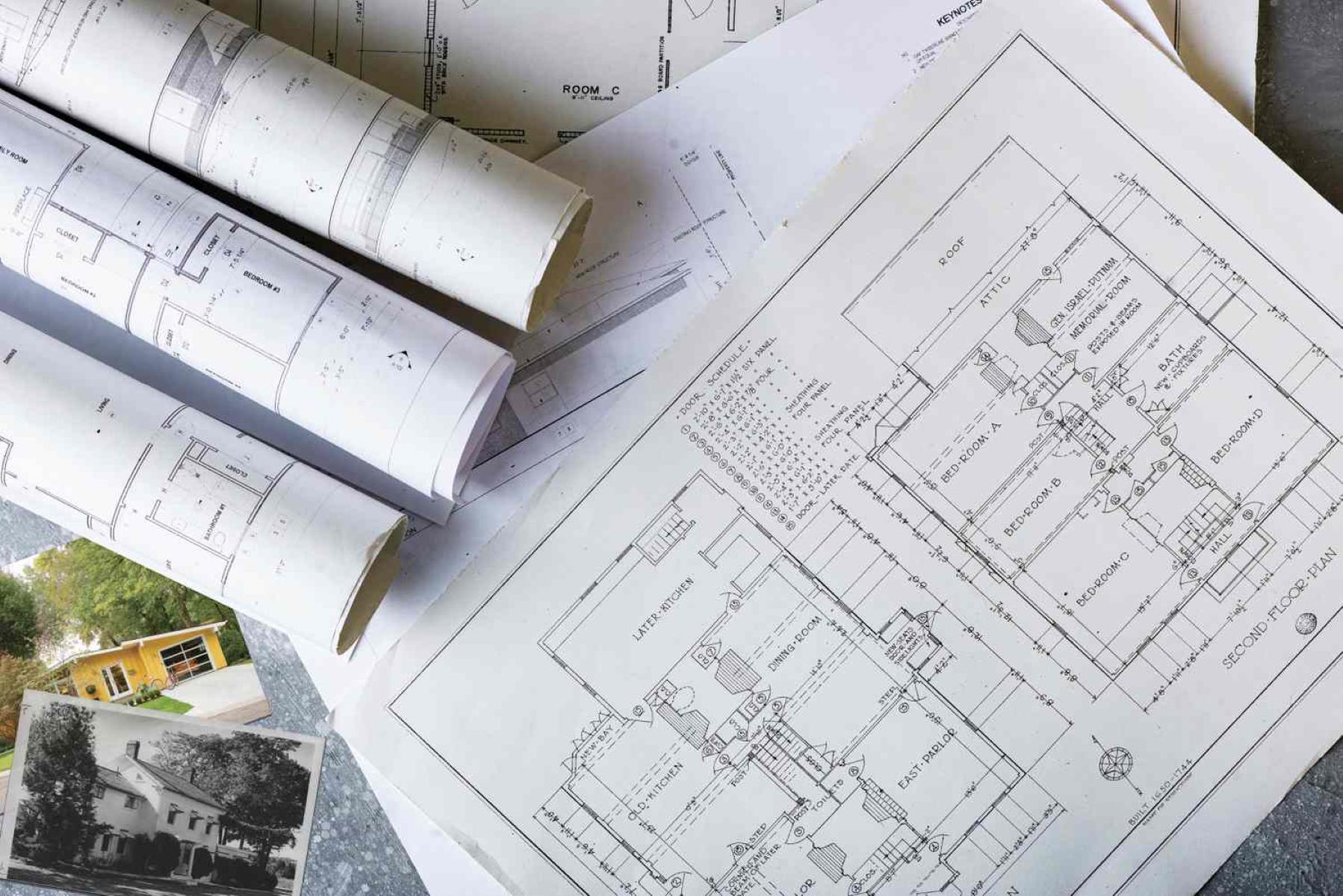
To fully comprehend the information presented on a blueprint, it’s important to familiarize yourself with the various sections and drawings it contains. Here are some common elements you will find on a blueprint:
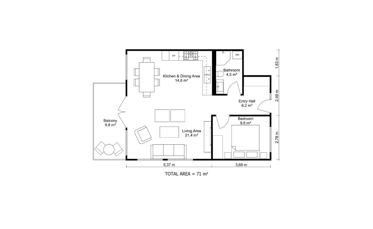
- Floor plans: These drawings provide a view of the building from above and show the layout of rooms, walls, and other structural elements.
- Elevations: Elevations show the vertical view of each side of the building, providing details on the exterior features, such as windows, doors, and architectural elements.
- Sections: Sections are drawings that cut through the building to show the internal structure and construction details.
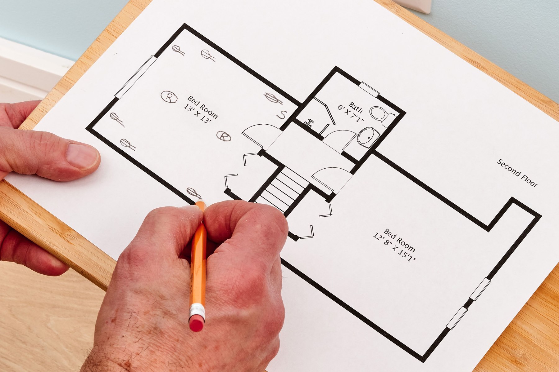
- Details: Detailed drawings focus on specific parts or components of the structure, such as staircases, windows, or electrical systems.
Now that we have a general understanding of blueprints, let’s explore how part dimensions are indicated on these drawings.
Reading Part Dimensions
Part dimensions on blueprints provide crucial information about the size, shape, and location of various components of a construction project. These dimensions ensure that every part is properly placed and aligned during the construction process.
When reading part dimensions on a blueprint, there are a few key elements to consider:
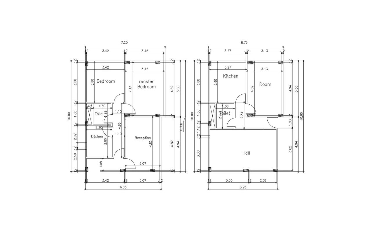
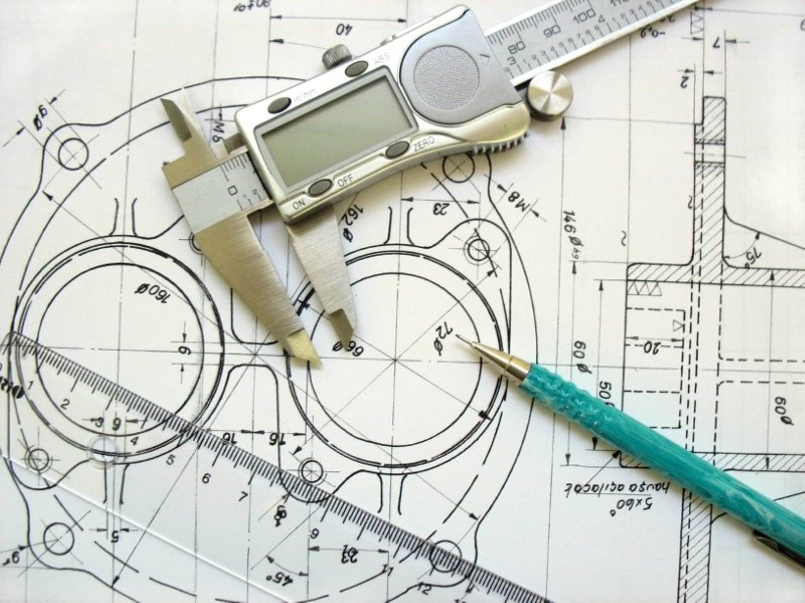
- Dimension lines: Dimension lines are straight lines with arrowheads at each end. They indicate the distance between two points and are labeled with a numerical value.
- Extension lines: Extension lines are used to extend the dimension lines to the edge of the object being dimensioned. They help to clarify which part of the object the dimension is referring to.
- Leader lines: Leader lines are used when the dimension lines cannot fit directly next to the object being dimensioned. They point from the object to the dimension line.
- Dimension values: The numerical values on dimension lines indicate the precise measurement of the corresponding part. These values are usually given in inches or millimeters, depending on the scale of the blueprint.
It’s important to pay attention to the orientation and alignment of the dimension lines and values. They should be clear and easy to understand, ensuring that there is no ambiguity in interpreting the part dimensions.
Additionally, part dimensions can be indicated using a variety of dimensioning techniques, which we will explore in the next section.
Now that we understand the basic components of reading part dimensions, let’s dive into the different types of dimensioning techniques commonly used on blueprints.
Types of Dimensioning on Blueprints
Dimensioning on blueprints can be done using different techniques, depending on the requirements and preferences of the architect or engineer. Here are some of the most common types of dimensioning techniques you may encounter:
- Aligned dimensioning: Aligned dimensioning involves placing dimensions in alignment with the object being dimensioned. This technique is commonly used when dimensions need to be clear and easy to read.
- Angular dimensioning: Angular dimensioning is used to specify the angle between two lines or surfaces. It is represented by a value in degrees.
- Radial dimensioning: Radial dimensioning is used to indicate the radius or diameter of a curved or circular object, such as a hole or a rounded corner.
- Chain dimensioning: Chain dimensioning is used when multiple dimensions are required in a continuous sequence. The dimensions are connected by thin, light lines to indicate their relationship.
- Baseline dimensioning: Baseline dimensioning involves aligning dimensions along a common baseline. This technique is commonly used when there are multiple features that need to be dimensioned relative to a single reference point.
Each dimensioning technique has its advantages and is suitable for different situations. Architects and engineers choose the most appropriate technique based on the specific requirements of the construction project.
Now that we have explored the different types of dimensioning techniques, let’s move on to understanding the basic and advanced dimensioning techniques used in blueprint reading.
When looking for part dimensions on a blueprint, start by locating the part on the drawing and then refer to the dimensions indicated in the title block, notes, or specific callouts for that part.
Basic Dimensioning Techniques
Basic dimensioning techniques are fundamental approaches used to indicate part dimensions on blueprints. These techniques provide clear and concise information about the size and location of different components. Here are some of the basic dimensioning techniques commonly used:
- Overall dimensions: Overall dimensions provide the total length, width, or height of a part. They are typically placed outside the part outline and are used to determine the overall size of the component.
- Linear dimensions: Linear dimensions indicate the length of a straight line or the distance between two points. They are placed parallel to the dimension line and are labeled with numerical values.
- Chain dimensions: Chain dimensions are used when it is necessary to show a series of consecutive dimensions. The dimensions are connected with thin, light lines, making it clear that they are part of a sequence.
- Ordinate dimensions: Ordinate dimensions are used when the location of a part feature is represented by distances measured from a common origin or a datum. They reduce the number of dimensions required and provide a more efficient way to convey the positioning information.
- Baseline dimensions: Baseline dimensions are used when multiple features need to be dimensioned relative to a common reference. They are aligned along a baseline, making it easy to understand the relationship between the dimensions.
These basic dimensioning techniques provide a solid foundation for conveying part dimensions on blueprints. It is important to understand and apply these techniques accurately to ensure that construction projects are executed with precision.
Now that we have covered the basic dimensioning techniques, let’s move on to exploring advanced dimensioning techniques used in blueprint reading.
Read more: How To Store Blueprints
Advanced Dimensioning Techniques
Advanced dimensioning techniques go beyond the basic approaches and provide additional information and clarity in specifying part dimensions on blueprints. These techniques are especially useful for complex and intricate components. Here are some of the advanced dimensioning techniques commonly used:
- Tolerance dimensions: Tolerance dimensions indicate the allowable variations in dimensions. They are accompanied by a tolerance value, which represents the acceptable range for the dimension. Tolerance dimensions ensure that parts can be manufactured within specified limits without compromising functionality or fit.
- Dual dimensioning: Dual dimensioning involves providing dimensions in both the imperial and metric systems. This technique is useful when working with international projects or when there is a need to accommodate different measurement systems.
- Leader dimensions: Leader dimensions are used to indicate dimensions that cannot be placed in the desired location directly next to the part. Leaders extend from the part to a nearby location where the dimension value is placed. This technique helps to avoid clutter and ensures clear communication of the dimension.
- Geometric dimensioning and tolerancing (GD&T): GD&T is a comprehensive system for specifying dimensions and tolerances based on geometric characteristics. It allows for a more precise and standardized communication of part requirements, especially for complex geometries and functional relationships.
- Reference dimensioning: Reference dimensioning is used when multiple instances of the same part are present in a construction project. Instead of dimensioning each instance separately, one reference dimension is used, and the remaining parts are marked as “Same as” or “Refer to” the reference dimension.
These advanced dimensioning techniques provide additional information and precision in conveying part dimensions on blueprints. Applying them correctly can help ensure that construction projects are executed with the necessary accuracy and precision.
Now that we have explored both basic and advanced dimensioning techniques, let’s take a look at the common symbols and abbreviations you may encounter on blueprints.
Common Symbols and Abbreviations on Blueprints
Blueprints often contain a variety of symbols and abbreviations that convey important information about the design and construction of a project. These symbols and abbreviations serve as shorthand communication tools, allowing architects, engineers, and construction professionals to convey complex details in a concise and standardized manner. Here are some common symbols and abbreviations you may encounter on blueprints:
- Arrowhead: An arrowhead is often used to indicate the direction or orientation of a component.
- Circle: A circle can represent a hole or a rounded surface.
- Square: A square can represent a flat surface or a feature that requires special attention.
- Triangle: A triangle can represent a reference point or a specific feature.
- Parallel lines: Parallel lines indicate that two surfaces are parallel to each other.
- Perpendicular lines: Perpendicular lines indicate that two surfaces are perpendicular to each other.
- Arrow: An arrow can indicate a specific location or a specific detail.
- Radius symbol: The radius symbol (R) is used to indicate the radius of a curved or rounded feature.
- Diameter symbol: The diameter symbol (Ø) is used to indicate the diameter of a round object or feature.
In addition to symbols, blueprints also incorporate a variety of abbreviations to convey information concisely. Here are some common abbreviations you may come across:
- FL: Floor Level
- EL: Elevation
- WD: Width
- HT: Height
- OD: Outside Diameter
- ID: Inside Diameter
- CR: Centerline Radius
- EA: Each
- AS: As Shown
Understanding these common symbols and abbreviations is essential for accurately interpreting the information presented on blueprints. It allows for efficient communication and reduces the chance of misinterpretation or errors during construction.
Now that we have covered the common symbols and abbreviations, let’s conclude our discussion on part dimensions on blueprints.
Conclusion
Blueprints are invaluable resources in the construction industry, providing detailed plans and specifications for projects. Part dimensions play a crucial role in ensuring that construction projects are executed accurately and according to design. By understanding how to read and interpret part dimensions on blueprints, architects, engineers, and construction professionals can effectively translate the design intent into reality.
In this article, we explored the fundamentals of understanding blueprints, including the different sections and drawings commonly found. We also discussed the process of reading part dimensions, emphasizing the importance of dimension lines, extension lines, leader lines, and dimension values.
We then delved into the various types of dimensioning techniques employed on blueprints, including aligned, angular, radial, chain, and baseline dimensioning. These techniques provide flexibility in conveying accurate measurements and positioning information.
Furthermore, we discussed the basic and advanced dimensioning techniques used in blueprint reading. The basic techniques, such as overall dimensions, linear dimensions, chain dimensions, ordinate dimensions, and baseline dimensions, establish the foundation for conveying part dimensions effectively. The advanced techniques, including tolerance dimensions, dual dimensioning, leader dimensions, geometric dimensioning and tolerancing (GD&T), and reference dimensioning, provide additional precision and information for complex components.
Lastly, we explored the common symbols and abbreviations on blueprints. These shorthand communication tools help convey specific features, dimensions, and other important details concisely.
By possessing a thorough understanding of blueprints and part dimensions, professionals in the construction industry can avoid mistakes, improve efficiency, and ensure precise execution of projects.
In conclusion, mastering the art of reading and interpreting part dimensions on blueprints is an essential skill for anyone involved in architecture, engineering, or construction. It is the key to successfully translating design concepts into tangible structures that meet specifications. So, embrace this knowledge, hone your skills, and let your expertise shine in the realm of blueprint dimensioning.
Frequently Asked Questions about How Are Part Dimensions Found On A Blueprint?
Was this page helpful?
At Storables.com, we guarantee accurate and reliable information. Our content, validated by Expert Board Contributors, is crafted following stringent Editorial Policies. We're committed to providing you with well-researched, expert-backed insights for all your informational needs.


0 thoughts on “How Are Part Dimensions Found On A Blueprint?”