Home>diy>Architecture & Design>How To Draw An Arrow In CAD

Architecture & Design
How To Draw An Arrow In CAD
Modified: January 9, 2024
Learn how to draw an arrow in CAD for architecture design projects. Step-by-step guide and tips for creating precise arrows in your CAD software.
(Many of the links in this article redirect to a specific reviewed product. Your purchase of these products through affiliate links helps to generate commission for Storables.com, at no extra cost. Learn more)
Introduction
Welcome to the world of Computer-Aided Design (CAD), where architects, engineers, and designers bring their ideas to life in a virtual realm. CAD software has revolutionized the way we create and visualize complex designs, providing an efficient and accurate solution for architectural and engineering projects.
One of the fundamental elements in CAD design is the use of arrows. Arrows are not only decorative but also serve an important purpose in conveying information, indicating direction, and providing clarity in drawings. Whether you are working on architectural floor plans, electrical schematics, or mechanical designs, knowing how to draw an arrow in CAD is an essential skill.
In this article, we will explore the various types of arrows commonly used in CAD and provide you with a step-by-step guide on how to draw arrows in CAD software. We will also share some tips and techniques to enhance the precision and aesthetics of your arrow drawings.
So, let’s dive into the world of CAD and discover the art of drawing arrows that will elevate the quality of your designs.
Key Takeaways:
- Master the art of drawing arrows in CAD to enhance the precision and aesthetics of your designs. Choose the right arrowhead style, ensure proper scaling, and utilize layers for efficient management.
- Elevate the quality of your CAD drawings by implementing tips and techniques for enhancing arrow drawings. Maintain consistency in lineweights, experiment with styles, and utilize color and patterns for visual engagement.
Read more: How To Print A CAD Drawing
Understanding CAD software
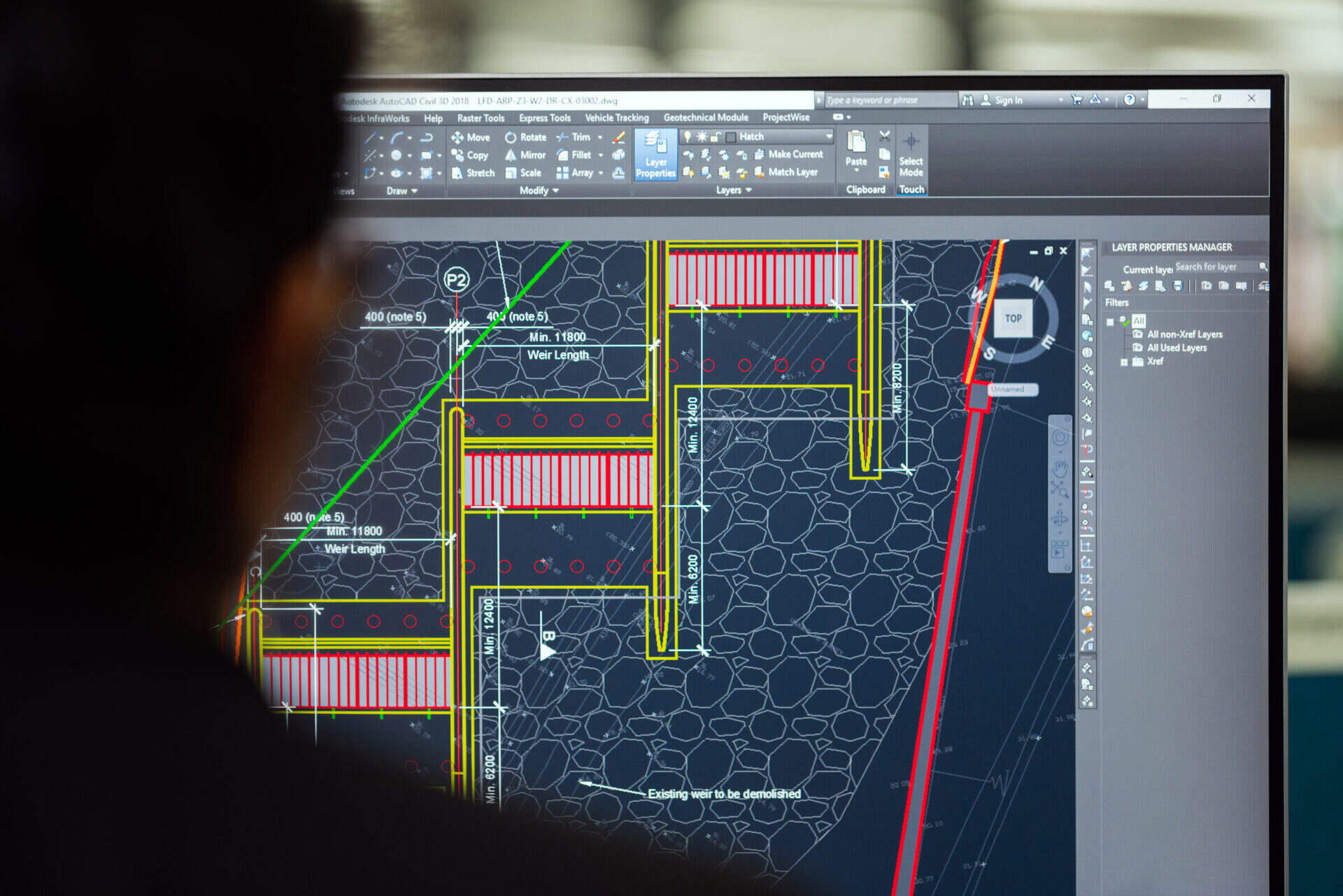
Before we delve into drawing arrows in CAD, it is important to have a basic understanding of CAD software and its capabilities. CAD software is specifically designed to create, modify, and analyze virtual 2D and 3D models.
Modern CAD software offers a wide range of tools and features that help designers and engineers create intricate designs with precision. These software programs provide a user-friendly interface, allowing users to easily navigate and manipulate the digital workspace.
CAD software is equipped with various drawing tools, including lines, arcs, circles, and polygons, which form the building blocks of complex geometries. These tools can be combined and manipulated to create accurate and detailed architectural, mechanical, or electrical drawings.
Besides drawing tools, CAD software also provides options for adding annotations, dimensions, and symbols to enhance the clarity and communicability of the designs. Arrows, in particular, are frequently used to indicate dimensions, point to important features, or highlight specific areas of the design.
Understanding the capabilities of your CAD software is essential, as different software programs may have slightly different workflows and features for drawing arrows. Familiarize yourself with the specific tools and functions of your chosen CAD software to make the most of its arrow-drawing capabilities.
Now that we have a grasp of CAD software and its purpose, let’s explore the different types of arrows commonly used in CAD drawings.
Types of arrows in CAD
In CAD drawings, arrows come in various shapes and styles, each serving a specific purpose. Understanding the different types of arrows available in CAD software will enable you to choose the most appropriate arrow for your design and effectively convey your intended message. Here are some commonly used types of arrows:
1. Standard Arrowhead: This is the most basic and widely used type of arrowhead in CAD drawings. It consists of a triangular shape with a straight line extending from the vertex. Standard arrowheads are versatile and suitable for indicating direction or pointing to specific areas of interest.
2. Closed Arrowhead: Similar to the standard arrowhead, the closed arrowhead has a triangular shape with a filled-in area at the tip. It provides a more solid and prominent look, often used to highlight important elements in the design.
3. Open Arrowhead: In contrast to the closed arrowhead, the open arrowhead has an empty or unfilled triangular shape at the tip. This type of arrowhead is commonly used to draw attention or indicate movement in a specific direction.
4. Dot Arrowhead: Instead of a triangular shape, the dot arrowhead features a small dot or circle at the end of the arrow. It is often used to indicate points of interest or key features in the design.
5. Dimension Arrow: Dimension arrows are specifically designed for indicating measurement values in CAD drawings. They typically have a straight line with dimension text placed on top or beside the line, providing precise information about the size or distance between objects.
6. Callout Arrow: Callout arrows are frequently used to highlight specific areas or provide additional information within a drawing. They usually have a curved or bent shape with a leader line connecting the arrowhead to the target area, creating a callout box for annotations or labels.
Now that you are familiar with different types of arrows, let’s move on to the step-by-step guide on how to draw arrows in CAD software.
When drawing an arrow in CAD, use the “Line” tool to create the shaft of the arrow, then use the “Arc” tool to create the arrowhead. You can also use the “Block” command to create a reusable arrow symbol.
Step-by-step guide to drawing an arrow in CAD
Now that you have a clear understanding of CAD software and the types of arrows available, let’s go through a step-by-step guide on how to draw an arrow in CAD. Keep in mind that the specific steps may vary slightly depending on the CAD software you are using, but the general concept remains the same.
- Open your CAD software and create a new drawing or open the existing one where you want to add the arrow.
- Select the appropriate drawing tool for creating lines or polylines (a continuous line made up of several segments).
- Choose the desired arrowhead style from the software’s arrowhead library or customize the arrowhead by specifying the dimensions and shape parameters.
- Start drawing the line or polyline where you want the arrow to begin. Use snapping tools or guidelines to ensure accuracy and alignment.
- Continue drawing the line or polyline in the desired direction, keeping in mind the length and angle of the arrow.
- Once you reach the endpoint of the arrow, apply the selected arrowhead style to the line or polyline.
- If needed, use the software’s editing tools to adjust the position or size of the arrowhead.
- Apply any additional annotations or labels associated with the arrow, such as dimensions, text, or callout boxes.
- Save your drawing, and you have successfully drawn an arrow in CAD!
Remember to practice and experiment with different arrowhead styles and techniques to find the ones that best fit your design and convey the intended message effectively.
Now that you know how to draw arrows in CAD, let’s explore some tips and techniques to enhance the precision and aesthetics of your arrow drawings.
Tips for enhancing arrow drawings in CAD
While drawing arrows in CAD, there are several tips and techniques you can employ to enhance the precision and aesthetics of your arrow drawings. These tips will help you create visually appealing and professional-looking designs. Here are some valuable tips to consider:
- Choose the right arrowhead style: Selecting the appropriate arrowhead style can significantly impact the clarity and visual appeal of your drawings. Consider the purpose of the arrow and choose a style that aligns with your design goals.
- Ensure proper scaling: Pay attention to the scaling of your arrows to ensure they are proportionate to the rest of the drawing. Use software tools to adjust the size of the arrowhead and length of the line for accurate representation.
- Use layers: Organize your drawings by utilizing layers. Assigning arrows to specific layers will enable you to manage and manipulate them more efficiently, especially when making changes or modifications to the design.
- Apply consistent lineweights: Maintain consistency in lineweights throughout your drawing to ensure that arrows are clearly visible. Thicker or bolder lines can make the arrows stand out and enhance their impact.
- Utilize color and patterns: Consider using colors or patterns to differentiate arrows based on their purpose or significance in the design. This can help convey information more effectively and make your drawings visually engaging.
- Check for accuracy: Before finalizing your drawings, double-check the accuracy of your arrows. Ensure that they are aligned correctly, point to the intended location, and convey the desired message accurately.
- Practice proper annotation: Add relevant annotations, dimensions, or labels to provide additional context or information associated with the arrow. Use appropriate text styles and sizes to ensure readability.
- Experiment with styles: Don’t be afraid to experiment with different arrow styles and explore customizations that suit your design aesthetic. This can help add uniqueness and creativity to your drawings.
By implementing these tips, you can elevate the quality of your arrow drawings in CAD and create designs that are precise, visually appealing, and effectively communicate your design intent.
Now that we have explored the tips and techniques for enhancing arrow drawings, let’s conclude our journey into the world of CAD arrows.
Read more: What Are CAD Drawings
Conclusion
CAD software has revolutionized the way we design and create complex models, enabling architects, engineers, and designers to bring their ideas to life in a virtual space. In the realm of CAD, arrows play a crucial role in conveying information, indicating direction, and enhancing the clarity of drawings.
In this article, we have explored the different types of arrows commonly used in CAD, such as standard arrowheads, closed arrowheads, open arrowheads, dot arrowheads, dimension arrows, and callout arrows. Each type has its own purpose and can be used to effectively communicate specific design elements.
We have also provided a step-by-step guide on how to draw arrows in CAD, emphasizing the importance of selecting the correct arrowhead style, scaling the arrow to its surroundings, utilizing layers, and ensuring consistency in lineweights. These tips and techniques are invaluable in creating arrow drawings that are precise, visually appealing, and communicative.
Remember to practice and experiment with different arrow styles to find the ones that best align with your design intent and aesthetic preferences. Pay attention to accuracy and use annotations or labels to provide additional context and information.
With the knowledge gained from this article, you are now equipped with the skills to draw arrows in CAD software like a pro. Use this knowledge to enhance the quality of your architectural, engineering, or design projects.
So, go ahead and unleash your creativity, incorporating arrows in your CAD drawings to guide, inform, and impress. Let your designs soar to new heights with the power of well-placed and precisely drawn arrows in the world of CAD.
Frequently Asked Questions about How To Draw An Arrow In CAD
Was this page helpful?
At Storables.com, we guarantee accurate and reliable information. Our content, validated by Expert Board Contributors, is crafted following stringent Editorial Policies. We're committed to providing you with well-researched, expert-backed insights for all your informational needs.








0 thoughts on “How To Draw An Arrow In CAD”