Home>diy>Architecture & Design>How Do CAD Engineers Use Geometry
Architecture & Design
How Do CAD Engineers Use Geometry
Modified: January 9, 2024
Learn how CAD engineers utilize geometry in architecture design. Discover the key techniques and tools used to create precise and intricate designs.
(Many of the links in this article redirect to a specific reviewed product. Your purchase of these products through affiliate links helps to generate commission for Storables.com, at no extra cost. Learn more)
Introduction
Welcome to the world of CAD engineering, where creativity meets precision. CAD (Computer-Aided Design) engineers play a crucial role in various industries, including architecture, manufacturing, and engineering. Their expertise lies in designing and developing digital models of structures and products, enabling efficient planning, analysis, and production.
In today’s modern world, CAD engineering has become an indispensable part of the design and manufacturing process. It allows engineers to visualize and manipulate models, test their functionalities, and optimize designs before going into production. One of the key elements that CAD engineers rely on is geometry, the branch of mathematics that deals with shapes, sizes, and properties of objects.
Geometry forms the foundation for all CAD designs. It provides the framework for creating and manipulating digital models, ensuring accuracy and precision in the engineering process. CAD engineers leverage geometry to bring their innovative ideas to life, using specialized software and tools designed to facilitate complex calculations and 3D modeling.
In this article, we will explore the various aspects of how CAD engineers utilize geometry in their everyday work. We will delve into the process of creating and importing geometric models, manipulating geometric objects, utilizing geometric constraints, and analyzing and evaluating designs. Additionally, we will discuss the importance of collaboration in CAD engineering and how geometry plays a crucial role in enabling effective teamwork.
So, whether you’re an aspiring CAD engineer looking to enter this exciting field or simply curious about the inner workings of CAD engineering, this article will provide you with a comprehensive understanding of how geometry is leveraged in CAD and its role in shaping the world of design and engineering.
Key Takeaways:
- Geometry forms the essential foundation of CAD engineering, enabling precise and accurate digital modeling. CAD engineers leverage geometry to create, manipulate, and analyze designs, driving innovation and problem-solving in various industries.
- Collaboration is crucial in CAD engineering, facilitated by CAD software’s features for real-time file sharing, version control, annotations, and virtual meetings. Effective collaboration ensures seamless integration of design components and high-quality end products.
Read more: How Is CAD Used In Engineering
Understanding CAD Engineering
CAD engineering is a multidisciplinary field that combines elements of design, engineering, and computer science. It involves the creation, modification, and optimization of digital models using specialized software and tools. CAD engineers work closely with architects, product designers, and engineers to develop precise and efficient designs for a wide range of applications.
At its core, CAD engineering aims to bridge the gap between conceptualization and realization. It allows engineers to transform their ideas into detailed and accurate models, facilitating better visualization and communication of design intent. CAD engineers use their technical expertise to solve complex problems, optimize designs, and streamline the manufacturing process.
One of the key advantages of CAD engineering is its ability to automate repetitive tasks and reduce the likelihood of human error. CAD software offers features such as parametric modeling, which allows engineers to create designs that are easily modifiable and adaptable. This enables rapid iterations and makes it easier to explore different design possibilities.
Furthermore, CAD engineering has revolutionized the collaboration process. With the ability to share and access design files digitally, engineers can work together in real-time, regardless of their physical location. This allows for efficient collaboration, feedback exchange, and simultaneous design modifications, resulting in faster development cycles and improved overall design quality.
To excel in CAD engineering, professionals need a strong foundation in mathematics, engineering principles, and technical skills. They must be proficient in using CAD software, including popular platforms like AutoCAD, SolidWorks, and CATIA. Additionally, CAD engineers should have a solid understanding of geometric concepts and the ability to apply them effectively in their designs.
With a clear understanding of CAD engineering, its advantages, and the skills required to succeed in the field, we can now dive deeper into the role that geometry plays in the CAD engineering process. In the next section, we will explore how geometric models are created and imported, establishing the basis for CAD engineering designs.
The Role of Geometry in CAD Engineering
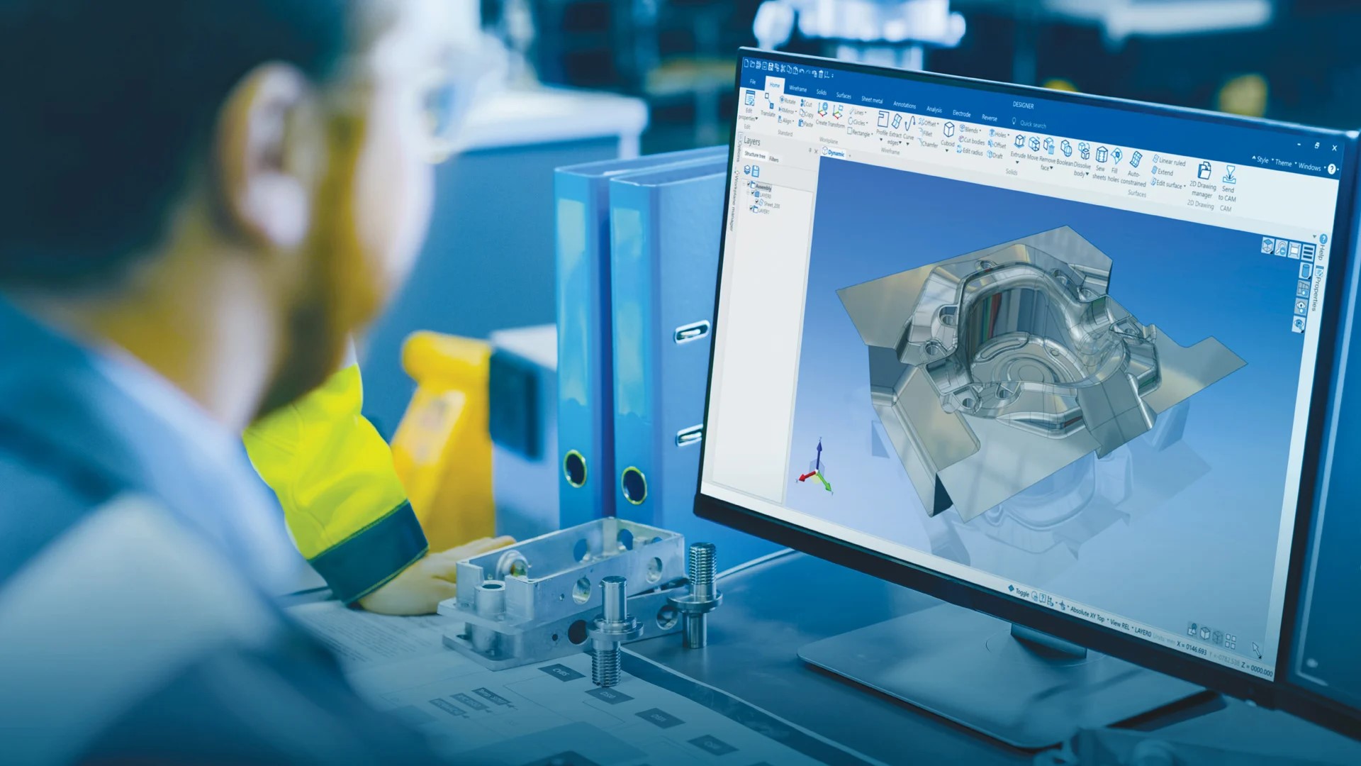
Geometry serves as the foundation for CAD engineering, providing the fundamental principles and tools needed to create precise and accurate designs. It encompasses the study of shapes, sizes, and properties of objects, which CAD engineers leverage to develop digital models that capture every detail of the real-world counterparts.
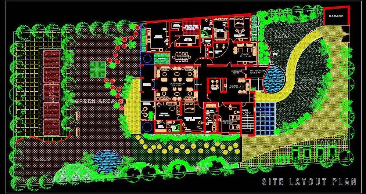
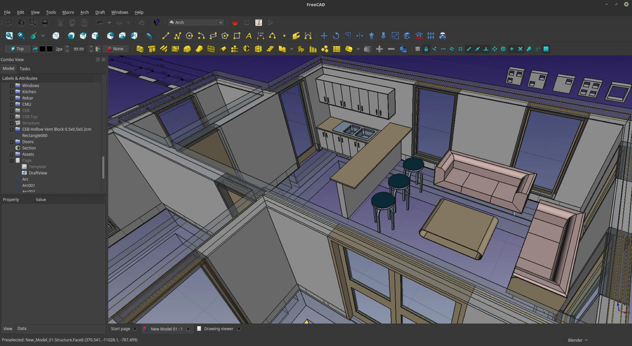
In CAD engineering, geometry is used to define the shape and dimensions of objects. CAD software allows engineers to create 2D and 3D representations of designs using geometric primitives such as points, lines, curves, and surfaces. These primitives form the building blocks of complex objects and serve as a framework for constructing intricate models.
One of the key benefits of geometry in CAD engineering is its ability to facilitate precise measurements. Engineers can define dimensions and constraints for geometric objects, ensuring that designs adhere to specific requirements and specifications. This enables accurate scaling, alignment, and positioning of different components within a design.
Geometry also plays a crucial role in visualization and rendering. CAD software utilizes geometric algorithms to transform mathematical representations of objects into realistic and visually appealing models. This allows engineers to visualize and evaluate designs from different perspectives, detecting any potential issues or areas for improvement.
Furthermore, geometry enables CAD engineers to simulate and analyze the functionality of designs. By applying principles of geometry, engineers can perform finite element analysis, stress testing, and fluid flow simulations to assess the performance and behavior of their designs under different conditions. This helps in identifying potential flaws, optimizing designs, and improving overall efficiency.
Additionally, CAD engineers use geometric constraints to ensure the integrity and stability of their designs. Geometric constraints define relationships between different elements, such as parallelism, perpendicularity, and concentricity. By applying these constraints, engineers can maintain the desired shape and alignment of objects even when modifications are made to the design.
Overall, geometry is a fundamental aspect of CAD engineering, providing the tools and principles needed to create, modify, and analyze digital models. It allows engineers to transform their ideas into tangible designs, ensuring accuracy, precision, and adherence to specifications. Without geometry, the world of CAD engineering would lack the essential framework necessary for innovation and problem-solving.
Now that we understand the role of geometry in CAD engineering, let’s explore the process of creating and importing geometric models in the next section.
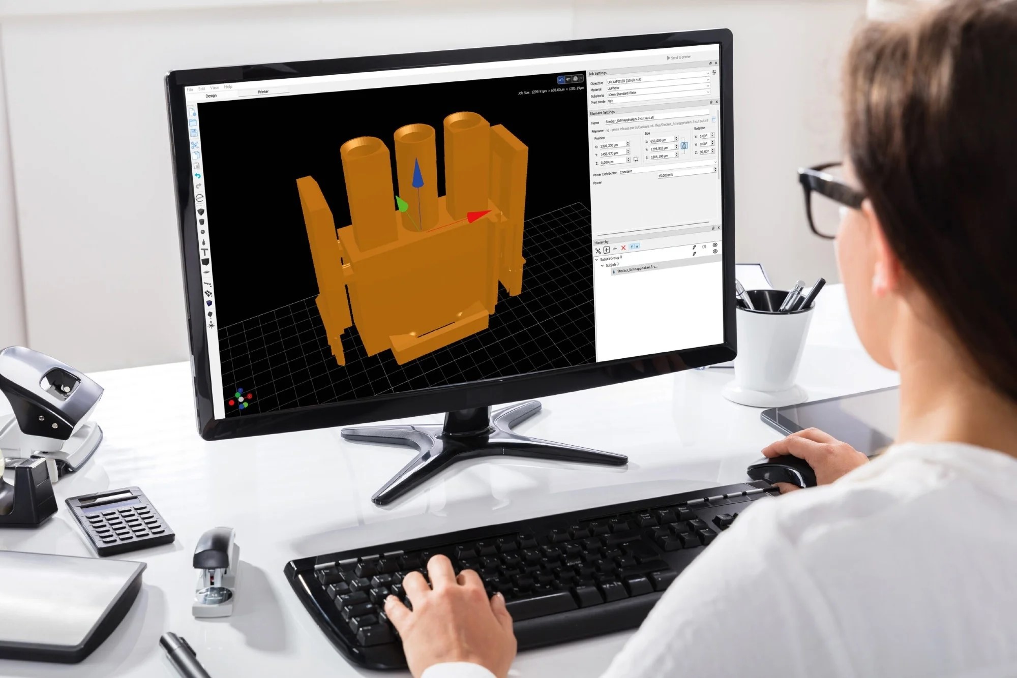
Creating and Importing Geometric Models
In CAD engineering, creating and importing geometric models is a crucial step in the design process. It involves converting design concepts into digital representations that can be further manipulated, analyzed, and optimized. CAD software provides engineers with a variety of tools and techniques to create and import geometric models with precision and ease.
When creating geometric models from scratch, CAD engineers start by defining the dimensions and features of the object. They use geometric primitives such as points, lines, arcs, and curves to construct the basic shapes that form the foundation of the model. These primitives can be combined, modified, and transformed to create intricate and complex designs.
CAD software often provides parametric modeling capabilities, allowing engineers to define relationships and constraints between different geometric elements. This feature enables engineers to easily modify designs and explore different design iterations without having to recreate the entire model. By adjusting parameters such as dimensions or angles, the entire model can be updated automatically, maintaining the desired design intent.
In addition to creating models from scratch, CAD engineers often need to import existing geometric models into their design environment. This can involve importing models from other CAD software, acquiring models from external sources, or utilizing pre-existing libraries of standard components. CAD software supports various file formats, such as STEP, IGES, and STL, which allow for seamless integration and collaboration across different platforms.
Importing geometric models brings numerous benefits to the CAD engineering process. It saves time and effort by allowing engineers to leverage existing designs and components rather than starting from scratch. This enables faster design iterations, promotes design reuse, and ensures consistency throughout projects.
However, when importing geometric models, CAD engineers must ensure that the models are compatible and aligned with their design requirements. They need to verify the accuracy of the imported models, check for any inconsistencies or errors, and make any necessary modifications to align them with their design specifications.
Once the geometric models are created or imported, CAD engineers can proceed with manipulating these models to further refine their designs. The next section will explore the various techniques and tools used by CAD engineers to manipulate geometric objects.
Manipulating Geometric Objects
In CAD engineering, manipulating geometric objects is a fundamental task that allows engineers to refine and optimize their designs. CAD software provides a wide range of tools and techniques to modify, transform, and manipulate geometric objects with precision and flexibility.
One of the key aspects of manipulating geometric objects is the ability to edit their geometry. CAD engineers can modify the shape, size, and position of geometric objects by using tools such as scaling, stretching, and rotating. This allows for customization and adaptation of designs to meet specific requirements and constraints.
Additionally, CAD software offers tools for mirroring and duplicating geometric objects. Engineers can create symmetrical designs by mirroring objects along a specified axis, or they can duplicate objects to create patterns or repetitions within their designs. This simplifies the design process and ensures consistency in the overall composition.
Another important aspect of manipulating geometric objects is the ability to perform Boolean operations. CAD software allows engineers to combine, subtract, or intersect different geometric objects to create complex shapes and cutouts. This enables engineers to create innovative designs by merging multiple objects or creating voids within existing shapes.
In some cases, engineers may need to deform or morph the shape of geometric objects to achieve specific design goals. CAD software provides tools for morphing, twisting, and bending objects, allowing engineers to create organic and freeform designs. This flexibility opens up new possibilities for creativity and enables the realization of unique design concepts.
Furthermore, CAD engineers can manipulate geometric objects by applying material properties and textures to their surfaces. This includes adjusting the color, transparency, and reflectivity of objects to enhance their visual appearance. By simulating real-world materials, engineers can better visualize and communicate their designs to clients, stakeholders, and production teams.
Additionally, CAD software provides tools for assembling and positioning geometric objects within a design. Engineers can align, snap, and connect objects to create assemblies and subassemblies. This enables engineers to simulate the final product and analyze the fit, functionality, and manufacturability of the design.
Overall, manipulating geometric objects is a crucial step in CAD engineering, allowing engineers to transform raw designs into refined and optimized models. By utilizing a variety of tools and techniques, CAD engineers can modify, transform, and manipulate geometric objects to achieve their desired design objectives.
Now that we understand how CAD engineers manipulate geometric objects, let’s explore the importance of geometric constraints in CAD engineering in the next section.
CAD engineers use geometry to create 2D and 3D models of products and structures. They use geometric principles to define shapes, sizes, and relationships between components, ensuring accuracy and precision in their designs.
Read more: Why Do We Use CAD
Using Geometric Constraints in CAD
Geometric constraints play a vital role in ensuring the accuracy, consistency, and reliability of CAD designs. By defining relationships between geometric objects, CAD engineers can maintain the desired shape, alignment, and behavior of their designs throughout the design process. Geometric constraints provide a set of rules that govern the interaction and positioning of objects, allowing for precise control and flexibility in design.
One of the commonly used geometric constraints in CAD engineering is the coincidence constraint. This constraint ensures that two or more points or objects lie on the same line or at the same location. It is useful for creating symmetrical designs and aligning components precisely within a design.
Another important constraint is the parallel constraint. It ensures that lines or edges remain parallel to each other, maintaining consistent spacing and alignment. The parallel constraint is especially useful when designing structures with multiple parallel elements, such as beams or support structures.
The perpendicular constraint ensures that lines or edges maintain a 90-degree angle relative to each other. This constraint is commonly used when designing right angles, such as corners or joints, to ensure precise alignment and geometric integrity.
Additionally, CAD software offers tangent and concentric constraints. These constraints ensure smooth transitions between curves or circles and ensure that objects share a common center point, respectively. They are particularly useful when designing objects with curved surfaces or circular patterns.
By applying geometric constraints, CAD engineers can maintain the intended relationships between objects, even when modifications are made to the design. If a constrained object is moved or modified, the CAD software automatically adjusts the other objects according to the specified constraints, ensuring consistency and preserving the design intent.
Geometric constraints enhance the efficiency and accuracy of CAD engineering by reducing errors and minimizing the need for manual adjustments. Engineers can focus on the creative aspects of the design knowing that the geometric constraints will ensure the desired relationships and dimensions are maintained.
Furthermore, geometric constraints enable rapid design modifications and iterations. By simply adjusting a few parameters or modifying a single object, multiple dependent objects can be automatically updated to reflect the changes. This saves time and effort, particularly when working on complex and intricate designs.
Overall, geometric constraints are a powerful tool in CAD engineering, providing precise control over the relationships and positioning of objects. They ensure consistency, accuracy, and efficiency in design, allowing CAD engineers to create intricate and complex models with ease.
Now that we understand the importance of geometric constraints in CAD engineering, let’s explore how CAD engineers analyze and evaluate geometric designs in the next section.
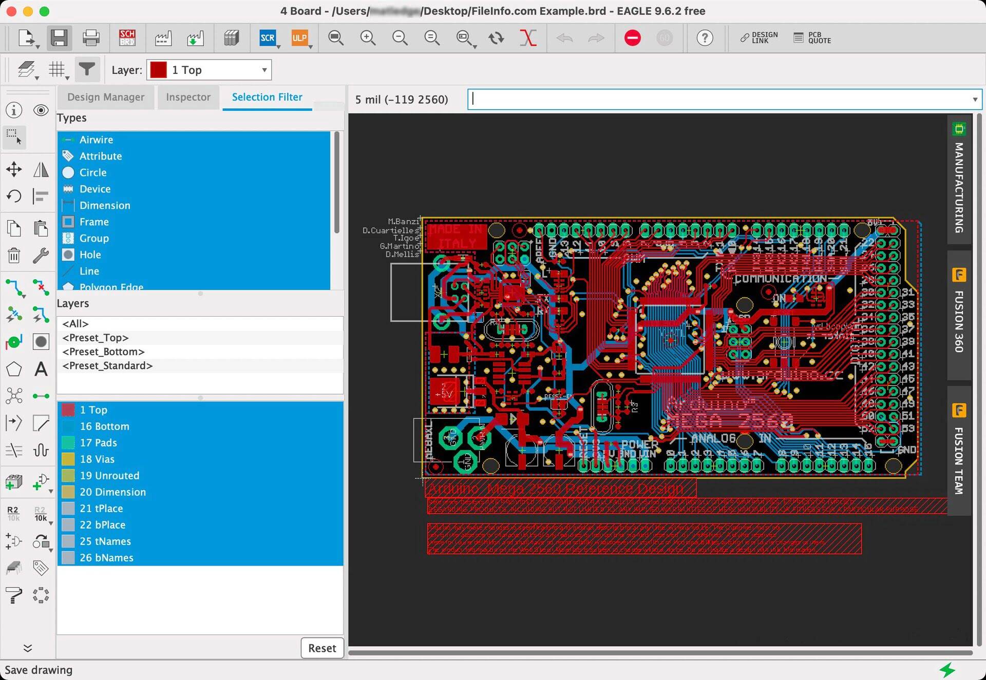
Analyzing and Evaluating Geometric Designs
In CAD engineering, analyzing and evaluating geometric designs is essential to ensure their functionality, structural integrity, and manufacturability. CAD software provides engineers with a range of tools and techniques to analyze and simulate various aspects of their designs, allowing for thorough evaluation and optimization.
One of the key analysis techniques is finite element analysis (FEA), which simulates the behavior of a design under different conditions, such as mechanical stress, heat transfer, or fluid flow. FEA allows engineers to evaluate the structural performance of their designs, identifying potential weak points, areas of stress concentration, or excessive deformations.
By analyzing the results of FEA simulations, engineers can identify areas for improvement and optimize their designs to ensure safety, durability, and efficiency. They can modify the geometry, adjust material properties, or introduce reinforcements to enhance the overall performance of the design.
Additionally, CAD software enables engineers to perform simulations and analyses specific to their design requirements. This includes thermal analysis to assess heat dissipation, flow analysis to study fluid behavior, or electrical analysis to evaluate circuits and connections. By conducting these analyses, engineers can ensure that their designs meet the desired specifications and perform as intended.
Another aspect of analyzing geometric designs is evaluating their manufacturability. CAD software provides engineers with tools to check for design flaws that may hinder the manufacturing process. This includes assessing tolerances, verifying clearances, and identifying potential manufacturing constraints.
By evaluating the manufacturability of a design early in the process, engineers can make necessary adjustments to ensure smooth production and reduce the likelihood of costly errors or rework later on.
Furthermore, CAD software enables engineers to perform virtual prototyping, allowing them to visualize and evaluate the assembly process of their designs. This involves checking for interferences, verifying the fit of components, and assessing the ease of assembly and disassembly.
Virtual prototyping helps engineers identify any potential issues or challenges in the manufacturing and assembly process, allowing for modifications or improvements before physical prototypes are manufactured.
Overall, analyzing and evaluating geometric designs in CAD engineering enables engineers to ensure the functionality, structural integrity, and manufacturability of their designs. By utilizing tools and techniques such as FEA, specific simulations, manufacturability checks, and virtual prototyping, engineers can optimize their designs, reduce risks, and save time and resources throughout the design and production process.
Now that we have explored the process of analyzing and evaluating geometric designs, let’s move on to discussing the importance of collaboration in CAD engineering.
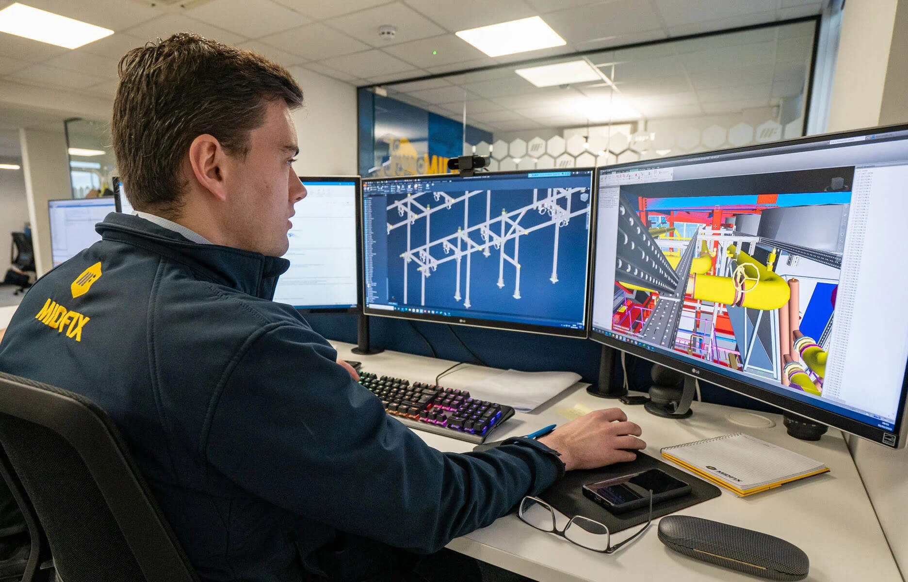
Collaborating with Other CAD Engineers
In the world of CAD engineering, collaboration is key to successful project completion. CAD engineers often work as part of a larger team, collaborating with other engineers, architects, and designers. Effective collaboration ensures seamless integration of different design components, efficient workflow, and a high-quality end product.
CAD software offers a variety of collaboration features that enable CAD engineers to work together seamlessly. One of the primary methods of collaboration is through file sharing and version control. CAD engineers can share design files with their colleagues, allowing them to work on the same project simultaneously and view real-time updates.
This eliminates the need for manual file transfers and ensures that all team members have access to the most up-to-date version of the design. File sharing and version control features also provide an audit trail, allowing engineers to track changes made to the design and revert to previous versions if necessary.
Collaboration in CAD engineering also extends to the exchange of feedback and annotations. CAD software offers mark-up tools that allow engineers to annotate designs, highlight specific areas, and provide comments for improvement or clarification. This fosters effective communication and ensures that all team members are on the same page regarding design modifications and requirements.
Moreover, CAD software enables engineers to collaborate on specific design tasks by dividing complex projects into smaller work packages. By assigning different sections of the design to individual team members, engineers can work in parallel, speeding up the overall design process and ensuring efficient utilization of resources.
Within a collaborative CAD environment, engineers can also share and access libraries of standard components, ensuring consistency and adherence to design standards. This promotes reusability, saves time, and maintains uniformity across different projects and design iterations.
Furthermore, virtual meetings and screen sharing capabilities offered by CAD software facilitate real-time discussions and decision-making among CAD engineers. Video conferences or online collaboration platforms allow team members to communicate, share ideas, address design challenges, and make important design decisions together, regardless of their geographical locations.
Professional networking and knowledge sharing within the CAD engineering community also contribute to collaboration. Engineers can connect with peers, join forums, attend conferences, and participate in training programs to exchange ideas, learn new techniques, and stay updated with the latest advances in CAD engineering.
In summary, collaboration is essential in CAD engineering to ensure smooth coordination between team members, efficient sharing of information, and the delivery of high-quality designs. CAD software provides the necessary tools and features to facilitate collaboration, whether it’s through file sharing, version control, mark-up tools, virtual meetings, or networking opportunities.
Now that we understand the importance of collaboration, let’s conclude our exploration of the role of geometry in CAD engineering.
Conclusion
In the world of CAD engineering, the role of geometry is essential to the design and development process. Geometry serves as the foundation for creating precise and accurate digital models, allowing CAD engineers to transform their ideas into tangible designs.
From creating and importing geometric models to manipulating and refining them, CAD engineers rely on geometry to ensure accuracy, consistency, and integrity in their designs. By utilizing geometric constraints, engineers can maintain the desired relationships between objects and ensure the reliability of their designs as they iterate and make modifications.
Geometry also plays a crucial role in analyzing and evaluating geometric designs. Through the use of simulations, finite element analysis, and manufacturability checks, CAD engineers can assess the functionality, performance, and suitability of their designs, making necessary adjustments to optimize their work.
Collaboration is another vital aspect of CAD engineering, enabling CAD engineers to work together seamlessly and integrate their design components effectively. CAD software provides collaboration features that allow for real-time file sharing, version control, annotations, and virtual meetings, ensuring efficient communication and cooperation among team members.
As CAD engineering continues to advance, it is important for CAD engineers to stay updated with the latest software tools, techniques, and industry trends. Networking and knowledge sharing within the CAD engineering community can greatly enhance collaboration and foster continuous improvement in the field.
In conclusion, geometry forms the backbone of CAD engineering, providing the principles and tools necessary for creating, manipulating, and evaluating geometric designs. By leveraging geometry effectively, CAD engineers can design innovative and precise models that drive advancements in various industries.
As technology continues to evolve, CAD engineering will continue to play a vital role in bringing creative ideas to life. By embracing the power of geometry and collaboration, CAD engineers can push the boundaries of design and contribute to the development of groundbreaking solutions.
Frequently Asked Questions about How Do CAD Engineers Use Geometry
Was this page helpful?
At Storables.com, we guarantee accurate and reliable information. Our content, validated by Expert Board Contributors, is crafted following stringent Editorial Policies. We're committed to providing you with well-researched, expert-backed insights for all your informational needs.


0 thoughts on “How Do CAD Engineers Use Geometry”