Home>diy>Architecture & Design>How To Make A CAD File

Architecture & Design
How To Make A CAD File
Modified: January 9, 2024
Learn how to create a CAD file for architecture design with our step-by-step guide. Start transforming your ideas into professional digital models today!
(Many of the links in this article redirect to a specific reviewed product. Your purchase of these products through affiliate links helps to generate commission for Storables.com, at no extra cost. Learn more)
Introduction
Welcome to the world of CAD (Computer-Aided Design)! In today’s digital age, designing and creating architectural masterpieces, engineering marvels, and stunning product prototypes has become easier than ever with the help of CAD software. CAD files are the backbone of any design project, providing the necessary specifications and visual representations for bringing ideas to life.
In this comprehensive guide, we will take you through the process of creating and working with CAD files, from choosing the right software to saving and exporting your designs. Whether you are a seasoned designer or a beginner looking to delve into the world of CAD, this article will provide you with the knowledge and tools you need to create professional-grade designs.
Before we dive into the technical details, let’s understand what CAD files are and why they are essential in the design process. CAD files are digital files that contain detailed information about the dimensions, geometries, and properties of a design. They serve as a blueprint for architects, engineers, and designers to visualize, analyze, and modify their creations virtually before moving on to the physical production.
With CAD software, designers can create precise, accurate, and realistic 2D and 3D models, making it an invaluable tool in a wide range of industries, including architecture, engineering, industrial design, and manufacturing. The ability to create, edit, and manipulate designs digitally saves time, reduces errors, and allows for more efficient collaboration and communication among team members.
Now, let’s explore the various aspects of working with CAD files, beginning with choosing the right CAD software for your needs.
Key Takeaways:
- Embrace the power of CAD software to create precise and realistic 2D and 3D designs, revolutionizing the way architectural, engineering, and product prototypes are brought to life with efficiency and accuracy.
- Master the art of CAD file creation, from choosing the right software to applying materials and textures, ensuring seamless collaboration, preservation, and compatibility of designs in the dynamic world of digital design.
Read more: How To Open CAD Files
Overview of CAD Files
CAD files are the digital representations of physical objects or structures created using CAD software. They are the backbone of any design project, providing a detailed and accurate description of the design elements, dimensions, and properties. CAD files can be categorized into two main types: 2D and 3D files.
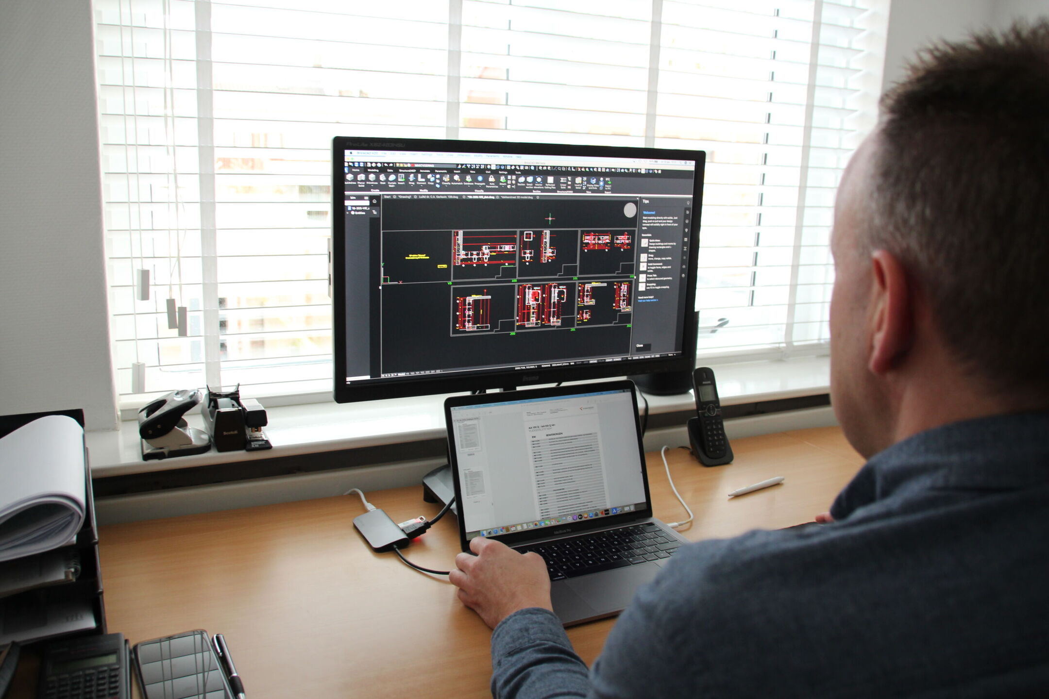
2D CAD files are created in a two-dimensional space and represent objects as flat drawings. They are commonly used for architectural floor plans, electrical schematics, site layouts, and mechanical drawings. 2D CAD files consist of lines, arcs, circles, and annotations that define the geometry and dimensions of the design.
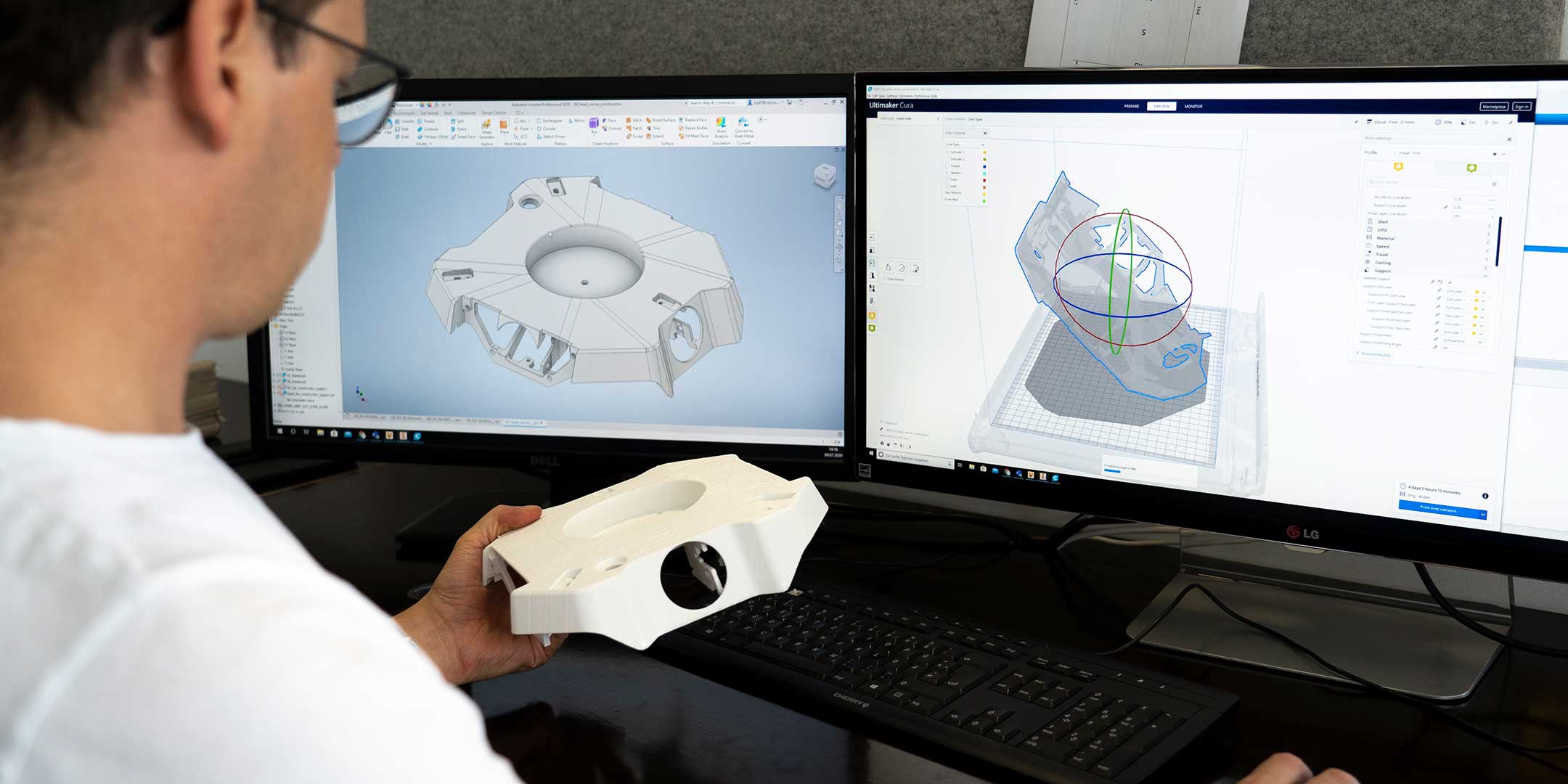
On the other hand, 3D CAD files offer a more immersive and realistic representation of objects by incorporating an additional spatial dimension. 3D CAD files allow designers to create digital models with depth and volume, enabling a more comprehensive visualization and analysis of the design. These files are widely used in architecture, product design, and engineering to create complex objects, assemblies, and simulations.
CAD files are usually saved in proprietary formats specific to the CAD software being used. However, there are also standardized formats that facilitate interoperability and ensure compatibility across different CAD platforms. Some common CAD file formats include DWG (AutoCAD), DXF (Drawing Exchange Format), STEP (Standard for the Exchange of Product Data), and IGES (Initial Graphics Exchange Specification).
In addition to geometry, CAD files can contain various other information such as materials, textures, annotations, and metadata. This additional data enhances the level of detail and realism in the design, making it more informative and accessible for further analysis and collaboration.
Now that we have a basic understanding of CAD files, let’s move on to the next step: choosing the right CAD software for your specific design needs.
Choosing the Right CAD Software
Choosing the right CAD software is crucial for a seamless and efficient design workflow. With the wide range of options available in the market, it’s important to consider your specific design needs, budget, user interface preferences, and compatibility with other software or industry standards. Here are a few factors to consider when selecting the right CAD software:
Design Specialization: Different CAD software packages cater to specific design disciplines. For example, if you are primarily focused on architectural design, software like AutoCAD or Revit may be a suitable choice. On the other hand, if you are more inclined towards mechanical design, SolidWorks or CATIA would be more suitable. Determine your primary design focus and choose software that specializes in that area.
User Interface: The user interface of CAD software plays a significant role in your productivity and ease of use. Look for software that has an intuitive and user-friendly interface, with easily accessible tools, customizable menus, and shortcut keys. Some software also offers a dark mode or customizable themes, which can reduce eye strain during long design sessions.
Compatibility: Consider the compatibility of CAD software with other software you use or might need to collaborate with. Ensure that your chosen software can import and export files in common CAD formats, allowing for smooth data exchange with clients, colleagues, or manufacturing facilities. Additionally, check if the software is compatible with your computer’s operating system.
Features and Functionality: Assess the features and functionality offered by different CAD software options. Look for features such as 2D and 3D modeling capabilities, parametric design functionality, rendering capabilities, simulation and analysis tools, and drafting and documentation features. Consider your specific design requirements and ensure that the software has the tools you need to facilitate your design process.
Community and Support: Consider the availability of a strong user community and support resources for the CAD software you are considering. A vibrant user community can provide valuable insights, tutorials, and forum discussions to help you master the software. Additionally, ensure that the software provider offers reliable technical support and regular software updates to address any issues or bugs that may arise.
Budget: Finally, consider your budget when selecting CAD software. Different software packages may vary significantly in terms of price, with some offering more advanced features at a higher cost. Evaluate your budget and choose software that provides the right balance between functionality and affordability.
Take the time to research and evaluate different CAD software options before making a decision. Consider reaching out to colleagues or industry professionals for their recommendations or trying out free trials or demos to get a feel for the software. Remember, choosing the right CAD software is an investment in your design process and can greatly impact your overall productivity and success.
Creating a New CAD File
Creating a new CAD file is the first step in bringing your design ideas to life. Whether you are starting from scratch or working on a modification of an existing design, CAD software provides the tools you need to create precise and accurate drawings. Here’s a step-by-step guide on how to create a new CAD file:
1. Launch the CAD Software: Open the CAD software on your computer. If you haven’t installed the software yet, follow the installation instructions provided by the software provider. Once the software is launched, you’ll be greeted with the interface and workspace.
2. Select the Drawing Template: When creating a new CAD file, you have the option to select a drawing template. Drawing templates contain predefined settings for units, scales, layers, and other properties that streamline the design process. Choose a template that aligns with your design requirements or create a custom template if needed.
3. Define the Drawing Units: It’s essential to define the units you’ll be using in your design. CAD software allows you to set the drawing units to match your desired measurement metric, such as millimeters, inches, or feet. This ensures that the dimensions in your CAD file are accurate and consistent with your intended scale.
4. Draw the Basic Geometry: Start by drawing the basic geometry of your design. Use tools like lines, circles, rectangles, or splines to create the shapes and outlines required. Pay attention to accuracy and precision while drawing, as these measurements will serve as the foundation for the entire design.
5. Add Detail and Features: Once the basic geometry is in place, you can start adding more detail and features to your design. Use tools like arcs, fillets, and chamfers to create rounded corners or smooth transitions between different elements. Experiment with different tools and techniques to achieve the desired look and functionality.
6. Create Layers and Assign Properties: Organize your design by creating layers and assigning properties to different elements. Layers help you group related objects together, making it easier to manage and control their visibility. Assign colors, line weights, and line types to different layers to enhance the visual representation of your design.
7. Apply Dimensioning: Add dimensions to your design to convey precise measurements and ensure that the design meets the required specifications. Use dimensioning tools to add linear dimensions, angular dimensions, or tolerances. Ensure that the dimensions are clear, legible, and placed appropriately to avoid confusion.
8. Annotate and Document: Annotate your design by adding text, notes, symbols, and other annotations as required. These annotations provide additional information or instructions related to the design. Create a documentation layer to keep all these annotations separate from the actual design elements.
9. Save and Backup: Regularly save your CAD file to prevent any loss of work. Use the save or save as option to specify the file location and name. Consider creating backups of your CAD files, either by manually copying them to external storage or using cloud-based storage services.
10. Revise and Modify: CAD designs are rarely finalized in the initial stages. As you progress with your design process, you may need to revise and modify the CAD file. Make use of the editing tools provided by the software to make changes, add new elements, or refine existing parts of the design.
By following these steps, you can create a new CAD file and start visualizing your design concepts with precision and accuracy. Remember to save your progress regularly and explore the various tools and techniques offered by your chosen CAD software to enhance your design capabilities.
Importing Existing Designs
Importing existing designs into your CAD software can save time and effort, especially when working on collaborative projects or making modifications to pre-existing designs. Most CAD software allows you to import designs from other CAD file formats or even from image files. Here’s a step-by-step guide on how to import existing designs into your CAD software:
1. Open the CAD Software: Launch the CAD software on your computer and open a new or existing project where you want to import the design.
2. Locate the Design File: Locate the design file that you want to import. This could be a CAD file from a different software or an image file such as JPEG or PNG.
3. Choose the Import Option: In your CAD software, look for the “Import” or “Insert” option. This option is usually found in the main menu or toolbar. Click on it to open the import dialog box.
4. Select the File Type: In the import dialog box, choose the appropriate file type of the design you want to import. Common file types include DWG, DXF, STEP, IGES, STL, or image formats like JPEG or PNG.
5. Adjust the Import Settings: Depending on the CAD software you are using, you may have the option to adjust import settings. These settings allow you to control the scale, units, and other properties of the imported design. Make any necessary adjustments to ensure the imported design fits correctly within your workspace.
6. Configure Placement: Determine where and how the imported design should be placed within your workspace. You may have options to specify the insertion point, rotation, or other placement parameters. Align the imported design with your existing project as desired.
7. Review and Confirm: Once you have made all the necessary adjustments, review the imported design to ensure its accuracy and compatibility with your project. Take the time to check if any elements need to be resized, modified, or repositioned.
8. Save the Project: After importing the design successfully, save your project to preserve the changes. It’s a good practice to use a different file name or create version backups to avoid overwriting the original design file.
9. Make Modifications: Now that the existing design is imported into your CAD software, you can begin making modifications or additions as required. Use the tools and features provided by the CAD software to edit, manipulate, or augment the imported design to meet your project’s needs.
10. Continue Working on the Design: With the imported design in place, you can now continue working on your project. You can add new elements, refine details, apply materials and textures, and perform any necessary analysis or simulations within the CAD software.
Importing existing designs into your CAD software offers flexibility and allows you to leverage pre-existing work or collaborate with other designers effectively. Take advantage of this feature to enhance your design process and streamline your workflow.
Read more: What Are CAD Files
Drawing Tools and Techniques
Drawing tools and techniques are the foundation of creating precise and accurate CAD designs. CAD software offers a wide range of tools and features that enable designers to create detailed and intricate drawings. Here are some essential drawing tools and techniques that can enhance your CAD design process:
1. Line and Polyline: The line tool allows you to draw straight lines between two points. It is the most basic and commonly used tool in CAD software. The polyline tool, on the other hand, enables you to draw a series of connected line segments as a single object. It is useful for creating complex shapes and outlines.
2. Circle and Arc: The circle tool allows you to create perfect circles by specifying the center point and radius. The arc tool is used to draw arcs or curved segments of circles. You can define the arc by specifying its center, radius, and start and end angles.
3. Rectangle and Polygon: The rectangle tool helps you draw precise rectangular shapes by specifying the corner points or dimensions. The polygon tool allows you to create regular polygons with a specified number of sides.
4. Spline and Curve: The spline tool lets you draw smooth and curved lines by defining a series of control points that influence the shape of the curve. It is useful for creating organic or free-flowing shapes. The curve tool allows you to draw curves based on mathematical equations or predefined curves.
5. Trim and Extend: The trim tool allows you to remove unwanted parts of lines, arcs, or other objects that intersect with other elements. The extend tool extends a line or an arc to reach another object, making it an efficient way to join or intersect lines.
6. Mirror and Offset: The mirror tool creates a mirrored copy of selected objects along a specified mirror line. This tool is useful for creating symmetrical designs or duplicating elements. The offset tool allows you to create parallel lines or curves at a specified distance from the original object.
7. Hatch and Fill: The hatch tool is used to apply a pattern or color fill to an enclosed area. It is commonly used for representing materials, textures, or sections in architectural or engineering drawings. The fill tool allows you to fill a closed area with a solid color.
8. Layers and Linetypes: Layers help you organize and manage different elements of your design. By assigning objects to specific layers, you can control their visibility, color, line weight, and linetype. This makes it easier to make edits or selectively display certain parts of the drawing.
9. Snap and Grid: The snap tool allows you to accurately place objects or vertices at specific points on the grid or existing objects. It keeps your drawings aligned and precise. The grid tool provides a visual reference of a predefined grid pattern, aiding in consistent spacing and alignment.
10. Dimensioning and Annotations: Dimensioning tools allow you to add dimensions to your drawings, specifying lengths, angles, and other measurements. Annotations, such as text or symbols, provide additional information or instructions related to the design. Proper dimensioning and annotations are crucial for clear communication and understanding of the design intent.
By mastering these drawing tools and techniques, you can create detailed and accurate CAD designs. Take the time to explore and practice with these tools to improve your proficiency and efficiency in CAD software.
When creating a CAD file, be sure to use layers to organize your design elements. This will make it easier to manage and edit the file as you work on it.
Adding Dimensions and Annotations
Adding dimensions and annotations to your CAD designs is essential for conveying precise measurements, providing clarity, and communicating important information. By using the dimensioning and annotation tools provided by CAD software, you can enhance the understanding and accuracy of your designs. Here are some key principles and techniques to consider when adding dimensions and annotations:
1. Select the Proper Dimensioning Type: CAD software provides various types of dimensions, such as linear dimensions, angular dimensions, radial dimensions, and ordinate dimensions. Choose the appropriate dimension type based on the specific object or feature you are dimensioning.
2. Define Dimension Styles: Dimension styles control the appearance of dimensions in your CAD drawings. You can customize the line types, arrowhead styles, text placement, text height, and other parameters to match your preferred standards or industry norms. Create and save different dimension styles for various purposes or design disciplines.
3. Place Dimensions Clearly: Dimensions should be placed in a clear and logical manner, avoiding clutter and overlapping. Ensure that dimensions do not obscure or interfere with the design elements. Place dimensions outside the main drawing area or use associative dimensions that can be moved and updated automatically along with the design modifications.
4. Provide Complete and Consistent Annotations: Annotations, such as text, symbols, or notes, help provide additional information or instructions related to the design. Use a consistent style and format for annotations throughout your CAD drawing. Ensure that the text is legible and easily understood, even when scaled or printed in different sizes.
5. Highlight Key Features: Annotations can be used to highlight important features or call attention to specific areas of the design. Use annotation tools like leader lines, balloons, or callouts to draw attention to critical elements or provide explanations for complex details.
6. Label and Annotate Components: In assembly drawings or complex designs, label and annotate individual components to provide clarity and assist in assembly or manufacturing processes. Use part numbers, labels, or specifications as annotations to facilitate understanding and referencing.
7. Include Tolerances and Geometric Symbols: If your design requires specific tolerances or geometric characteristics, include them as annotations. Utilize geometric symbols, such as concentricity, perpendicularity, or symmetry, to communicate precise requirements for manufacturing or inspection.
8. Coordinate with Design Standards and Conventions: Ensure that your dimensions and annotations follow recognized design standards and conventions. Familiarize yourself with industry-standard dimensioning practices and symbols, such as ANSI, ISO, or ASME standards, to ensure consistency and compatibility with other design professionals.
9. Check for Clarity, Completeness, and Accuracy: Before finalizing your dimensions and annotations, review them to ensure they provide clear and accurate information. Double-check for any missing dimensions, incorrect measurements, or inconsistencies in labeling. These small details can greatly impact the accuracy and interpretation of the design.
10. Update and Modify as Needed: As your design evolves or requires modifications, ensure that the dimensions and annotations are updated accordingly. CAD software often offers tools to automatically update dimensions when the design changes. Regularly review and revise the dimensions to maintain accuracy throughout the design process.
By following these principles and techniques, you can add dimensions and annotations that enhance the understanding, functionality, and usability of your CAD designs. Precision and clarity in dimensioning and annotations are crucial for ensuring proper communication and successful realization of your design intent.
Working with 3D Models
Working with 3D models in CAD software offers a whole new level of depth and realism to your designs. It allows you to visualize and manipulate objects in three dimensions, providing a comprehensive understanding of spatial relationships. Here are some key considerations and techniques for working with 3D models in CAD:
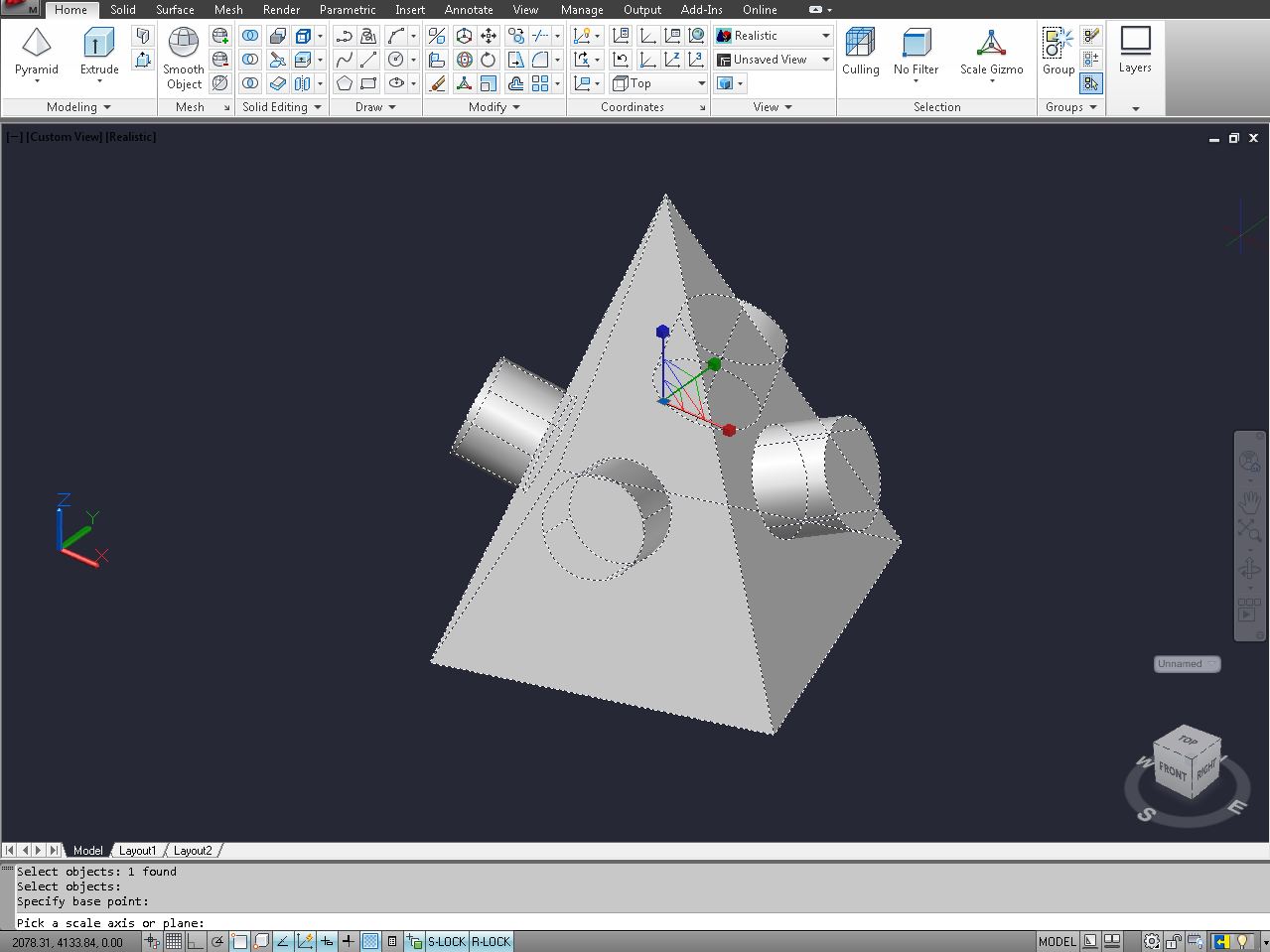
1. Creating 3D Geometry: To create 3D models, you will use a combination of tools such as extrusion, lofting, sweeping, and revolving. These tools allow you to translate, rotate, and scale 2D shapes into the third dimension. Experiment with different techniques to create complex and realistic 3D geometry.
2. Coordinate Systems: Understand the concept of coordinate systems in 3D modeling. CAD software uses a Cartesian coordinate system with X, Y, and Z axes to define the position and orientation of objects in 3D space. Familiarize yourself with changing views, creating isometric or perspective views, and manipulating the coordinate system to better visualize and work with your 3D models.
3. Sculpting and Modifying Surfaces: CAD software often includes sculpting and modification tools that allow you to manipulate the surfaces of your 3D models. These tools can be used to smooth or fillet edges, add filigree details, or create more organic shapes. Experiment with different techniques to refine the appearance and aesthetics of your 3D models.
4. Applying Constraints and Parameters: In 3D modeling, you can apply constraints and parameters to different components or elements within your models. Constraints define relationships between different parts, such as maintaining parallelism, perpendicularity, or coincident positioning. Parameters allow you to control and modify specific dimensions or properties of your 3D models easily.
5. Assembly and Interference Checking: If you are working on a project involving multiple components or parts, utilize the assembly tools provided by your CAD software. These tools allow you to position, align, and join different objects together to create complex assemblies. Check for interferences or clashes between components to ensure a proper fit and functionality.
6. Rendering and Visualization: Take advantage of rendering capabilities to bring your 3D models to life. Apply materials, textures, and lighting to enhance the visual appeal and realism of your designs. Experiment with different rendering techniques and settings to achieve the desired look and feel of your 3D models.
7. Analyzing and Simulating: CAD software often provides tools for analyzing and simulating the behavior of your 3D models. These tools can include stress analysis, fluid flow simulations, or motion studies. Utilize these features to evaluate the performance, structural integrity, or functionality of your designs and make necessary adjustments.
8. Collaborative Work: With 3D models, collaboration becomes even more critical. CAD software offers features for sharing and collaborating with team members or clients. Utilize features such as model sharing, version control, or cloud-based platforms to streamline collaboration, gather feedback, and ensure everyone is working with the latest version of the 3D models.
9. File Management and Organization: As your 3D models become more complex, ensure that you maintain a proper file management and organizational system. Create folders or layers to group related components, parts, or assemblies. Maintain a naming convention for your files to avoid confusion and make it easier to locate and manage your 3D models.
10. Continuous Learning and Exploration: The world of 3D modeling is vast and continually evolving. Keep up-to-date with the latest features and techniques offered by your CAD software. Explore online resources, tutorials, or attend workshops to expand your knowledge and push the boundaries of what you can achieve with 3D models.
By applying these techniques and considerations, you can fully utilize the power and flexibility of 3D modeling in your CAD designs. Embrace the creative possibilities that working in 3D provides and let your imagination shape extraordinary designs.
Applying Materials and Textures
Applying materials and textures to your 3D models in CAD software adds realism and visual appeal to your designs. By simulating real-world materials and surfaces, you can enhance the presentation and representation of your models. Here are some key considerations and techniques for applying materials and textures in your CAD designs:
1. Material Libraries: Most CAD software comes with built-in material libraries that contain a wide range of pre-defined materials, such as metals, plastics, woods, glass, or fabrics. Explore these libraries to find materials that closely match the appearance of your design elements.
2. Custom Materials: If you cannot find a suitable material in the pre-defined libraries, you can create custom materials by adjusting properties such as color, reflectance, transparency, roughness, or texture mapping. Custom materials allow you to achieve unique visual effects or simulate specific materials accurately.
3. Texture Mapping: Texture mapping is the process of applying 2D images or patterns, known as textures, onto the surface of 3D models. This technique adds detail and realism to your models, such as simulating wood grain, fabric patterns, or surface imperfections. Experiment with different textures and mapping methods to achieve the desired visual effect.
4. Bump and Displacement Mapping: Bump mapping and displacement mapping are techniques used to add depth and surface variations to your models. Bump mapping simulates the illusion of surface irregularities by modifying how light interacts with the surface. Displacement mapping physically modifies the geometry of the 3D model based on the texture’s grayscale values, resulting in more pronounced surface details.
5. Reflectance and Specularity: Reflectance and specularity properties affect how objects in your CAD models reflect light. Adjusting these properties can simulate materials with different levels of shininess, roughness, or glossiness. Pay attention to the reflectance and specularity settings to accurately represent the material characteristics of your design elements.
6. Lighting and Environment: Consider the lighting conditions and environment in which your 3D models will be displayed. Adjust the lighting settings within your CAD software to accurately represent how light interacts with your materials and textures. Experiment with different lighting setups to create the desired mood or emphasize specific design features.
7. Transparency and Opacity: Use transparency and opacity settings to simulate materials that allow light to pass through, such as glass or liquids. Adjusting these properties can create realistic effects and showcase internal features of your models. Strike a balance between transparency and performance, as too many transparent surfaces can impact the rendering speed.
8. UV Mapping: UV mapping is the process of mapping 2D texture coordinates onto a 3D model’s surface. It helps align textures accurately along the model’s geometry. By properly applying UV mapping, you can avoid texture stretching or distortion and ensure seamless and realistic material application on your models.
9. Rendering Options: Take advantage of the rendering options provided by your CAD software. Different rendering techniques, such as ray tracing or global illumination, can enhance the visual quality of your materials and textures. Adjust settings like anti-aliasing, shadows, or ambient occlusion to achieve high-quality renderings.
10. Test and Iterate: Preview and test your materials and textures regularly throughout the design process. Make adjustments as needed to achieve the desired visual effect. Evaluate the appearance of your models from different angles, under different lighting conditions, and in various environments to ensure accurate representation.
By carefully considering these techniques and principles, you can bring your CAD models to life by applying realistic materials and textures. Experiment with different options, explore new textures, and take advantage of advanced rendering capabilities to create visually stunning and compelling designs.
Read more: How To Flatten CAD File
Saving and Exporting CAD Files
Saving and exporting CAD files is an essential step in preserving your design work and sharing it with others. Proper file management ensures that your designs are easily accessible and compatible with different software and platforms. Here are some key considerations and techniques for saving and exporting CAD files:
1. Save Regularly: Make it a habit to save your CAD files frequently to avoid any potential loss of work. Use the “Save” or “Save As” option in your CAD software to designate a location on your computer or network drive where the file will be stored. Consider creating a folder structure to maintain organization and easy access to your CAD files.
2. Use Version Control: In collaborative design projects, it is essential to keep track of different versions of the CAD file. Consider using version control software or techniques to maintain a history of revisions, allowing you to revert to older versions if necessary. This ensures that everyone involved is working with the most up-to-date file.
3. File Formats: CAD software typically offers several file formats to save your designs. Choose a file format that is widely supported and compatible with other CAD software or design tools. Common file formats include DWG, DXF, STEP, IGES, and STL. Verify the compatibility requirements of your intended audience before exporting.
4. Maintain Original and Backup Files: It is wise to keep a backup of your original CAD file in its native format to retain all the layers, properties, and settings. Additionally, consider exporting your CAD files to other file formats (such as PDF or JPEG) for easy sharing and viewing by clients, stakeholders, or non-CAD users.
5. Include Supporting Documentation: When exporting CAD files, it may be necessary to provide supporting documentation, such as assembly instructions, bill of materials, or design specifications. Depending on the requirements of your project, include these files or create a separate document that accompanies the CAD file to ensure clarity and understanding.
6. Check for File Size and Compression: CAD files can often be large in size due to the complex geometry and detailed information they contain. Before sharing or exporting, consider optimizing the file size by compressing or simplifying the model without compromising its integrity. This helps reduce storage requirements and improves file transfer speed.
7. Protect Intellectual Property: If confidentiality or intellectual property protection is a concern, consider using password protection or encryption features provided by your CAD software. These features allow you to restrict or control access to your CAD files, protecting your designs from unauthorized use or modifications.
8. Follow Industry Standards and Regulations: Depending on the industry or field you are working in, there may be specific standards or regulations regarding CAD file formats and requirements. Ensure that your exported CAD files comply with any applicable standards or regulations to meet industry expectations and facilitate compatibility.
9. Collaborative File Sharing: Utilize collaboration platforms or cloud-based services to share your CAD files with team members, clients, or stakeholders. These platforms often provide version control, access control, and real-time collaboration features, allowing for efficient and secure file sharing and collaboration.
10. Documentation and Metadata: As you save or export CAD files, consider including relevant documentation and metadata within the files or through accompanying files. This can include information such as project names, dates, author details, design revisions, or any other valuable information that aids in understanding and managing the CAD files.
By following these best practices for saving and exporting CAD files, you can ensure the preservation, accessibility, and compatibility of your design work. Proper file management and organization simplify collaboration and sharing, allowing your designs to be seamlessly integrated into larger projects or utilized by others in the design ecosystem.
Conclusion
In conclusion, CAD software has revolutionized the way we design and create. It provides us with powerful tools and capabilities to bring our ideas to life with precision and accuracy. Throughout this comprehensive guide, we have explored various aspects of working with CAD files, from choosing the right software to saving and exporting our designs.
We began by understanding the importance of CAD files as the digital blueprints of our designs. Whether in 2D or 3D, CAD files serve as the foundation upon which we build our creations. We then delved into choosing the right CAD software, considering factors such as design specialization, user interface, compatibility, features, community support, and budget.
We learned how to create new CAD files, including selecting drawing templates, defining units, drawing basic geometries, adding details, and organizing the design elements using layers and annotations. Importing existing designs into our CAD software became a breeze, enabling us to leverage previous work or collaborate with other designers seamlessly.
Through the use of essential drawing tools and techniques, we learned how to create precise and accurate CAD drawings. Adding dimensions and annotations ensured that our designs effectively communicated measurements, details, and additional information to aid in the realization of our vision.
As we ventured into the world of 3D modeling, we discovered techniques for working with 3D models, including creating 3D geometry, sculpting surfaces, applying constraints, and analyzing the functionality and performance of our designs. Finally, we explored the art of applying materials and textures to our models, bringing them to life with realism and visual appeal.
With the completion of our designs, we embarked on the journey of saving and exporting CAD files. By regularly saving our work, using version control, selecting appropriate file formats, including supporting documentation, and following industry standards, we ensured the accessibility, protection, and compatibility of our design files.
In this fast-paced technological era, CAD software continues to evolve and advance, enabling designers to push the boundaries of creativity and innovation. By continually honing our skills, embracing new tools and techniques, and staying aware of industry trends, we can thrive in this exciting realm of digital design.
So, whether you are an aspiring designer or a seasoned professional, armed with the knowledge and techniques acquired through this guide, you are well-equipped to navigate the world of CAD with confidence and create designs that inspire and captivate. Embrace the power of CAD and let your imagination soar!
Frequently Asked Questions about How To Make A CAD File
Was this page helpful?
At Storables.com, we guarantee accurate and reliable information. Our content, validated by Expert Board Contributors, is crafted following stringent Editorial Policies. We're committed to providing you with well-researched, expert-backed insights for all your informational needs.


0 thoughts on “How To Make A CAD File”