Home>diy>Architecture & Design>How Is CAD Used In Engineering

Architecture & Design
How Is CAD Used In Engineering
Modified: September 1, 2024
Learn how CAD is used in engineering and the role it plays in architecture design. Discover the benefits and applications of this powerful tool.
(Many of the links in this article redirect to a specific reviewed product. Your purchase of these products through affiliate links helps to generate commission for Storables.com, at no extra cost. Learn more)
Introduction
Computer-Aided Design, commonly known as CAD, has revolutionized the field of engineering. This powerful technology has transformed the way engineers design and develop products, structures, and systems. With its ability to create accurate and detailed digital models, CAD has become an invaluable tool for engineers in various industries, including aerospace, civil, mechanical, and electrical engineering.
CAD software allows engineers to create, modify, analyze, and optimize designs with precision and efficiency. It provides a virtual platform where designers can visualize and simulate their ideas before they are brought to life. This not only saves time and resources but also enables engineers to identify and rectify design flaws early in the development process.
In this article, we will explore the basics of CAD and delve into its numerous applications in engineering. We will discuss the benefits of using CAD in engineering design, manufacturing, structural analysis, fluid dynamics analysis, electrical engineering, civil engineering, aerospace engineering, and mechanical engineering. By the end, you will have a comprehensive understanding of how CAD is used across different engineering disciplines.
Key Takeaways:
- CAD revolutionizes engineering by providing efficient design, simulation, and collaboration tools across various disciplines, from mechanical and aerospace to civil and electrical engineering.
- With CAD, engineers can visualize, validate, and optimize designs, leading to increased efficiency, accuracy, and innovation in the development of products, structures, and systems.
Read more: How Do CAD Engineers Use Geometry
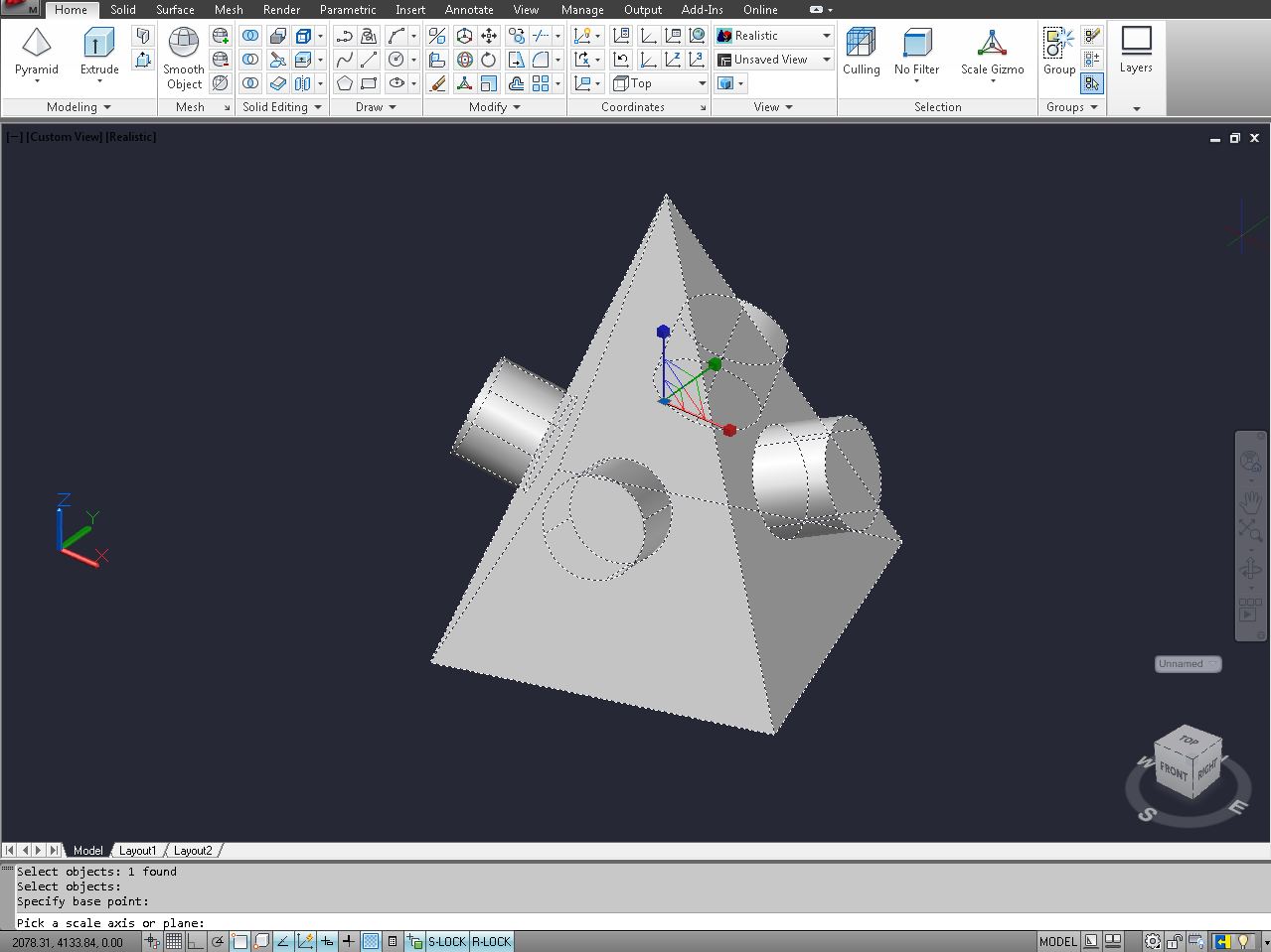
CAD Basics
Before diving into the various applications of CAD in engineering, let’s first understand the basics of CAD and how it works. CAD is a software tool that allows engineers to create, edit, and view digital models of their designs. These virtual models can range from simple 2D drawings to complex 3D models that represent the real-world objects or systems being designed.
CAD software provides a wide range of tools and features that enable engineers to draw precise geometries, apply materials and textures, define dimensions and constraints, and add annotations to their designs. These tools simplify the design process, making it easier for engineers to iterate and modify their designs as needed.
One of the key advantages of CAD is its ability to create parametric models. Parametric modeling allows engineers to define and control the relationships between different components in the design. For example, if the length of a shaft is changed, all the components that are connected to it will automatically adjust their positions and dimensions accordingly. This saves time and effort when making design changes and ensures the integrity of the overall design.
CAD software also offers a variety of visualization tools that allow engineers to view their designs from different angles, zoom in and out, and even animate the motion of their assemblies. This helps engineers gain a better understanding of how their designs will look and function in the real world.
Collaboration is another key aspect of CAD. Multiple engineers can work on the same design simultaneously, making it easier to divide tasks and share ideas. CAD software also allows for easy sharing and transfer of design files, enabling engineers to collaborate with colleagues and stakeholders regardless of their physical location.
It is important to note that CAD is not just limited to 2D and 3D modeling. It also encompasses other functionalities such as simulation and analysis tools, rendering capabilities, and drafting and documentation features. These additional tools help engineers validate and optimize their designs, generate accurate technical drawings, and communicate their ideas effectively to other stakeholders.
Now that we have a basic understanding of CAD, let’s explore the many benefits it offers in the field of engineering.
Benefits of Using CAD in Engineering
The use of CAD in engineering brings numerous benefits that enhance the design and development process. Here are some key advantages of using CAD:
- Increased Efficiency: CAD software allows engineers to create designs faster and more accurately compared to manual drafting. The ability to use pre-designed components and libraries reduces the need to start from scratch, saving valuable time in the design process.
- Improved Accuracy: CAD ensures precision and accuracy in design by providing tools for precise measurements, constraints, and mathematical calculations. This minimizes errors and discrepancies, resulting in higher-quality designs.
- Design Visualization: CAD enables engineers to visualize their designs in 2D or 3D, providing a comprehensive understanding of how the end product will look and function. This allows for better design evaluation and decision-making during the development process.
- Design Iteration and Modification: With CAD, engineers can easily modify and iterate their designs without having to start from scratch. This flexibility allows for quick and efficient design changes based on feedback and requirements.
- Design Validation: CAD software offers simulation and analysis capabilities, allowing engineers to test and validate their designs before they are built. This helps identify potential issues, optimize performance, and minimize costly mistakes during the manufacturing and assembly processes.
- Collaboration and Communication: CAD facilitates seamless collaboration between engineers, designers, and other stakeholders involved in the project. Design files can be easily shared, reviewed, and revised, ensuring efficient communication and alignment of ideas throughout the design process.
- Cost and Time Savings: By reducing manual drafting time, minimizing errors, and optimizing designs, CAD helps save both time and money in the engineering process. It streamlines workflows, reduces material waste, and speeds up time-to-market.
- Documentation and BOM Generation: CAD software automates the generation of technical drawings, bill of materials (BOM), and other documentation required for manufacturing and assembly. This ensures accurate and consistent documentation throughout the entire product lifecycle.
- Adaptability and Scalability: CAD designs can be easily modified and adapted to different design requirements, variations, or customer preferences. This scalability allows for efficient design customization and mass production.
- Sustainability and Environmental Impact: CAD enables engineers to analyze the environmental impact of their designs, such as energy consumption, material usage, and waste generation. This helps in making informed decisions to create more sustainable and environmentally friendly products.
The benefits of using CAD in engineering are undeniable. Its efficiency, accuracy, visualization capabilities, design validation tools, and collaboration features greatly contribute to the success of engineering projects across various industries.
CAD Applications in Engineering Design
CAD plays a crucial role in the design phase of engineering projects. Whether it’s designing complex machinery, intricate electronics, or innovative structures, CAD software offers a wide range of applications to support engineers in their design processes. Here are some key areas where CAD is extensively used in engineering design:
- Conceptual Design: CAD allows engineers to quickly create preliminary designs and explore different ideas. It enables them to sketch and visualize concepts in 2D or 3D, helping to refine and communicate early-stage designs.
- Detail Design: Using CAD, engineers can create detailed and dimensioned models of their designs. They can add features, define material properties, and specify manufacturing requirements to develop a comprehensive design with accurate measurements and annotations.
- Parametric Modeling: CAD software provides parametric modeling features, enabling engineers to create intelligent models with defined relationships and constraints. This allows for easy design modifications and adaptability to varying design requirements.
- Assembly Design: CAD facilitates the assembly of complex systems by allowing engineers to create digital representations of individual components and then assemble them virtually. This helps in identifying interferences, ensuring proper fit and alignment, and optimizing the overall assembly process.
- Mechanical Design: CAD is widely used for mechanical design tasks, such as creating 3D models of machine parts, assemblies, and mechanisms. It enables engineers to analyze motion, calculate forces and stresses, and evaluate the performance of mechanical systems.
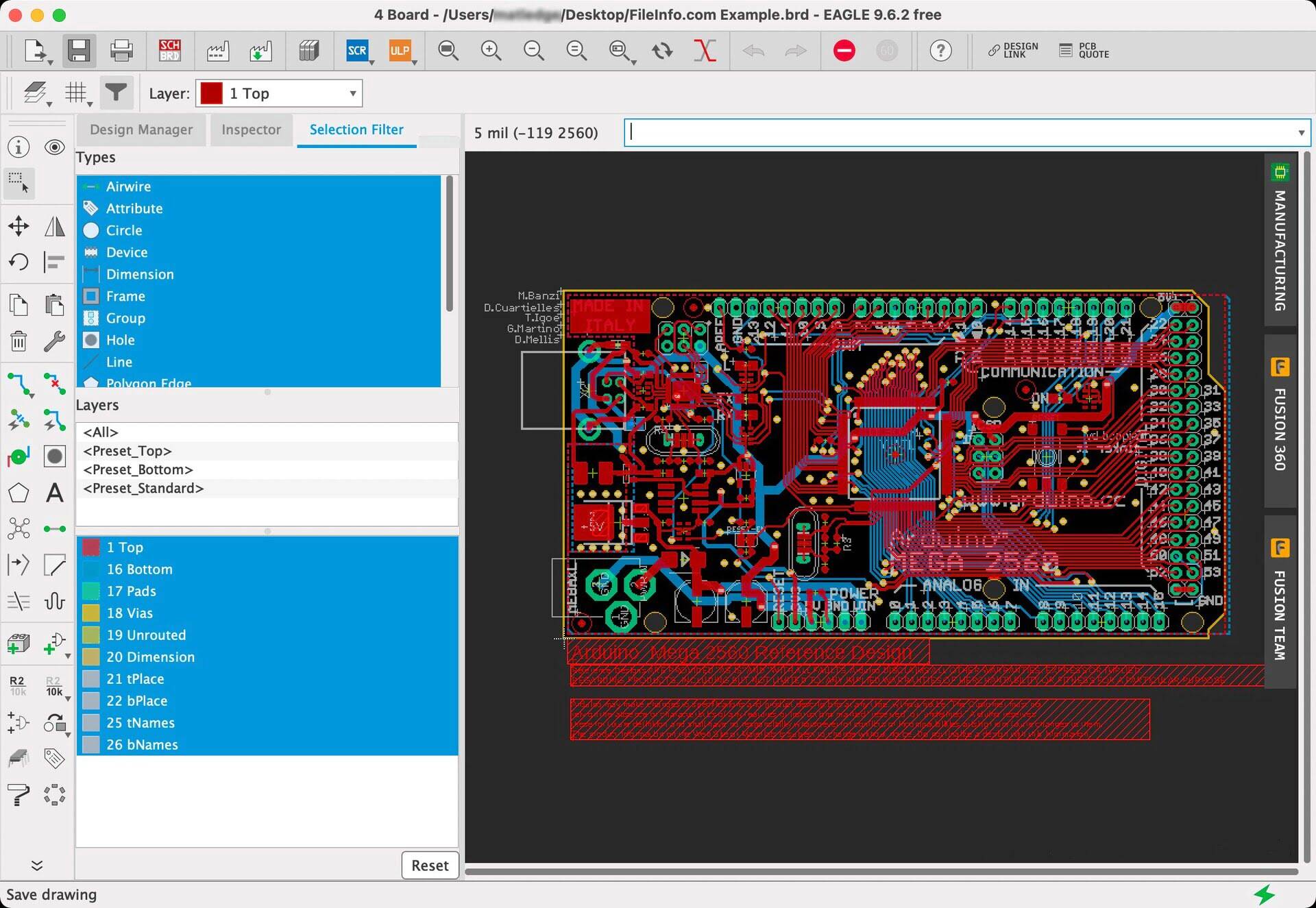
- Electronics Design: CAD software tailored for electronics design enables engineers to create schematic diagrams, design printed circuit boards (PCBs), and simulate electrical circuits. It helps in optimizing component placement, routing traces, and ensuring proper electrical functionality.
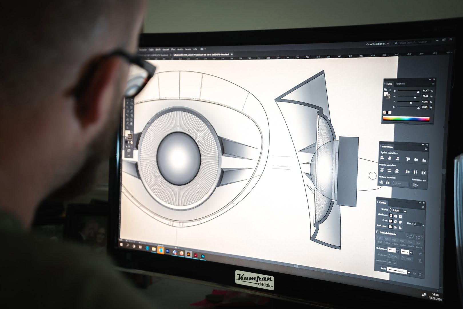
- Product Visualization: CAD allows engineers to visualize their designs in photorealistic renderings, making it easier to showcase products to clients and stakeholders. It helps in marketing, visualization, and aids in design communication.
- Design Validation and Analysis: CAD software provides simulation and analysis tools to evaluate the performance and behavior of designs. Engineers can perform stress analysis, fluid flow analysis, heat transfer analysis, and other tests to verify the design’s suitability for its intended purpose.
- Design Documentation: CAD automates the creation of technical drawings, assembly instructions, and other documentation required for manufacturing and assembly. It ensures accurate and consistent documentation throughout the design process.
- Collaborative Design: CAD enables real-time collaboration among engineers working on the same design. Design files can be shared, reviewed, and revised, allowing for efficient communication and collaboration across multidisciplinary teams.
The use of CAD in engineering design offers significant advantages in terms of speed, accuracy, collaboration, and the ability to visualize and validate designs effectively. It empowers engineers to bring their ideas to life and create innovative solutions across a wide range of industries.
CAD Applications in Manufacturing
CAD plays a pivotal role in the manufacturing industry, where it is extensively used to improve efficiency, accuracy, and productivity throughout the production process. From designing and prototyping to production planning and quality assurance, CAD software offers a wide range of applications in manufacturing. Here are some key areas where CAD is essential in the manufacturing industry:
- Product Design: CAD software is used to create detailed and precise 3D models of products, including their individual components and assemblies. These models serve as the foundation for the manufacturing process, helping engineers visualize and refine the design before production.
- Tooling and Fixture Design: CAD allows engineers to design specialized tools, jigs, and fixtures needed for the manufacturing process. These tools aid in accurate and efficient assembly, machining, and quality control.
- Manufacturing Process Design: CAD is used to plan and optimize the manufacturing process, including selecting the appropriate machinery, defining assembly sequences, and determining the optimal manufacturing parameters.
- Prototyping: CAD software makes it easier to create prototypes by generating accurate 3D models that can be 3D printed or CNC-machined. Prototyping not only helps engineers validate and test the design but also reduces errors and costs in the final production phase.
- Toolpath Generation: CAD software integrates with computer-aided manufacturing (CAM) software to generate toolpaths for CNC machines. These toolpaths define the tool’s movement, speeds, and feeds, ensuring precise and efficient machining operations.
- Simulation and Visualization: CAD software provides simulation capabilities to analyze and visualize the manufacturing process. Engineers can simulate manufacturing steps, check for potential collisions, and identify any issues before they occur in the real production environment.
- Production Planning: CAD allows engineers and production managers to plan and organize the production process more efficiently. It assists in material management, production scheduling, and resource allocation, optimizing resources and ensuring timely delivery of products.
- Quality Assurance: CAD offers tools for quality control and inspection processes. Engineers can compare manufactured parts against the CAD models to validate dimensional accuracy, detect variations, and identify any quality issues early on.
- Documentation and Work Instructions: CAD automates the creation of detailed manufacturing drawings, work instructions, and assembly documentation. These documents guide the production team, ensuring consistency and accuracy throughout the manufacturing process.
- Data Management: CAD software helps manage and control manufacturing data, including design revisions, product configurations, and bill of materials (BOM). It ensures that the correct and up-to-date information is available to the manufacturing team.
CAD revolutionizes the manufacturing industry by improving design accuracy, streamlining the production process, enhancing quality control, and reducing time-to-market. It empowers manufacturers to produce high-quality products efficiently and effectively.
Read more: What Are The Advantages And Disadvantages Of Using CAD Systems To Create Engineering Drawings
CAD Applications in Structural Analysis
CAD software plays a crucial role in structural analysis, enabling engineers to analyze and optimize the behavior and performance of structures under various loads and conditions. With CAD-based structural analysis tools, engineers can evaluate the strength, stability, and integrity of structures to ensure they meet safety requirements and design specifications. Here are some key applications of CAD in structural analysis:
- Finite Element Analysis (FEA): CAD software integrates with FEA tools to simulate the behavior of structures under different types of loads and conditions. By breaking down the structure into small elements, FEA helps engineers calculate stress, strain, displacement, and other parameters to assess structural integrity.
- Structural Modeling: CAD enables engineers to create detailed 3D models of structures, accurately representing the geometry, materials, and connections. These models serve as the foundation for structural analysis and allow engineers to visualize the behavior and response of the structure under load.
- Load Analysis: CAD-based structural analysis tools facilitate the application and distribution of loads on the structure. Engineers can define various types of loads, such as dead loads, live loads, wind loads, and seismic loads, to assess the overall stability and strength of the structure.
- Stress and Strain Analysis: By utilizing FEA and CAD, engineers can calculate stress and strain distributions within the structure. This analysis helps identify areas of high stress and potential failure points, enabling engineers to make design modifications for improved structural performance.
- Deflection and Deformation Analysis: CAD software allows engineers to assess the deflection and deformation of structures under load. This analysis helps ensure that the structure remains within acceptable limits of deformation, preventing excessive flexing or failure.
- Buckling Analysis: CAD-based structural analysis tools enable engineers to evaluate the stability of slender structures against buckling, which is a mode of failure caused by compression. By predicting critical buckling loads and modes, engineers can optimize the design for enhanced stability.
- Optimization: CAD software offers optimization capabilities that allow engineers to automatically explore different design options and parameters. By defining optimization goals, such as minimizing weight or maximizing strength, engineers can find the most efficient and cost-effective structural design.
- Dynamic Analysis: CAD-based structural analysis tools assist in evaluating the dynamic response of structures to dynamic loads, such as vibrations and earthquakes. Engineers can simulate and analyze the behavior of structures under different dynamic conditions to ensure their robustness and resilience.
- Code Compliance: CAD software incorporates design codes and standards, ensuring that the structural design complies with industry-specific regulations and safety requirements. Engineers can validate their designs against these codes to ensure structural integrity.
- Documentation and Reporting: CAD-based structural analysis tools generate detailed reports and documentation of analysis results. This helps engineers communicate their findings, recommendations, and design changes to stakeholders, creating a transparent and evidence-driven decision-making process.
The integration of CAD and structural analysis tools empowers engineers to design structurally sound and efficient structures. It enables them to iterate and optimize designs, ensuring safety, functionality, and cost-effectiveness in various applications, including buildings, bridges, towers, and other infrastructure projects.
CAD is used in engineering to create detailed 2D and 3D models of products and structures. It helps engineers visualize and analyze designs, make modifications, and generate accurate technical drawings for manufacturing.
CAD Applications in Fluid Dynamics Analysis
CAD software plays a critical role in the field of fluid dynamics analysis, where it is used to model and simulate the behavior of fluids and their interactions with structures. By combining CAD and computational fluid dynamics (CFD) tools, engineers can optimize the design of fluid systems, improve performance, and ensure the efficient flow of fluids. Here are some key applications of CAD in fluid dynamics analysis:
- Fluid Flow Modeling: CAD software allows engineers to create accurate 3D models of fluid systems, including pipes, ducts, channels, and complex geometries. These models serve as the basis for simulating and analyzing fluid flow behavior.
- Flow Visualization: CAD-based fluid dynamics analysis tools provide advanced visualization capabilities to help engineers observe and interpret fluid flow behavior. They can visualize velocity profiles, pressure distributions, streamlines, and turbulence effects to gain insights into the performance of the fluid system.
- Pressure Drop Analysis: By integrating CAD with CFD tools, engineers can predict and analyze pressure drops across fluid systems. This analysis helps optimize pipe sizes, identify flow restrictions, and minimize energy losses, enhancing the overall efficiency of the fluid system.
- Heat Transfer Analysis: CAD software enables engineers to analyze heat transfer phenomena within fluid systems. They can assess temperature distributions, heat transfer rates, and thermal gradients to optimize the design of heat exchangers, cooling systems, and other thermal management applications.
- Flow Simulation: CAD-based fluid dynamics analysis tools simulate fluid flow behavior within the designed system. Engineers can analyze parameters such as velocity profiles, pressure distributions, turbulence, and flow separation to optimize the design and ensure proper flow characteristics.
- Design Optimization: By using CAD and fluid dynamics analysis tools, engineers can perform optimization studies to improve the design of fluid systems. Parameters such as pipe diameters, flows rates, or component placements can be adjusted to achieve desired performance targets, such as minimizing pressure drop or maximizing heat transfer.
- Multiphase Flow Analysis: CAD software assists in analyzing fluid systems with multiple phases, such as gas-liquid or liquid-solid interactions. Engineers can study phenomena such as two-phase flow, bubble formation, and sedimentation to optimize the design of systems involving mixtures or particulate flows.
- Turbulence Analysis: CAD-based fluid dynamics analysis tools help engineers evaluate and understand turbulence effects in fluid systems. By analyzing parameters such as turbulent viscosity, turbulent kinetic energy, and turbulent dissipation rate, engineers can optimize designs for reduced turbulence and increased efficiency.
- Environmental Analysis: CAD software enables engineers to assess the environmental impact of fluid systems. They can simulate fluid flow and dispersion patterns to study issues like pollution dispersion, air quality, and contamination risks, aiding in the design of environmentally conscious systems.
- Performance Prediction: CAD-based fluid dynamics analysis tools allow engineers to predict the performance of fluid systems under different operating conditions. This helps in sizing and selecting components, optimizing system configurations, and predicting system behavior over a wide range of operating conditions.
The integration of CAD and fluid dynamics analysis tools empowers engineers to design and optimize fluid systems with improved efficiency, performance, and operational characteristics. It enables them to predict and analyze fluid flow behavior, make informed design decisions, and ensure optimal performance in applications such as HVAC systems, pipelines, turbines, and various industrial processes.
CAD Applications in Electrical Engineering
CAD software plays a vital role in electrical engineering by facilitating the design and development of electrical systems and circuits. With CAD tools specifically tailored for electrical engineering, engineers can create, analyze, and optimize electrical designs in a digital environment. Here are some key applications of CAD in electrical engineering:
- Schematic Design: CAD software allows electrical engineers to create detailed schematic diagrams of electrical circuits. They can add components, define connections, and annotate the design, providing a graphical representation of the circuitry.
- PCB Design: CAD-based PCB design tools enable engineers to layout and design the physical structure of printed circuit boards (PCBs). They can place components, route traces, and define layers, ensuring proper connectivity and electrical performance.
- Component Libraries: CAD incorporates extensive libraries of electrical components, such as resistors, capacitors, transistors, and integrated circuits. Engineers can choose components from these libraries, ensuring accurate representation and precise modeling of electrical designs.
- Simulation and Analysis: CAD tools offer simulation and analysis capabilities for electrical circuits. Engineers can simulate circuit behavior, analyze voltage and current characteristics, and detect potential issues or failure points before prototyping or manufacturing.
- Signal Integrity Analysis: CAD software helps engineers analyze and optimize the signal integrity of high-speed digital circuits. They can assess impedance matching, crosstalk, and noise margins to ensure proper signal transmission and minimize signal degradation.
- Power Distribution: CAD-based electrical design tools assist in designing power distribution systems. Engineers can plan and optimize the routing of power lines, calculate power losses, and ensure efficient power distribution across the system.
- Electromagnetic Compatibility (EMC) Analysis: CAD software enables engineers to analyze and optimize the electromagnetic compatibility of electrical designs. They can assess the susceptibility of components to external interference and ensure compliance with EMC standards.
- Thermal Analysis: CAD-based electrical design tools facilitate thermal analysis of electrical components and systems. Engineers can predict temperature distributions, assess thermal dissipation, and ensure proper heat management in power-intensive circuits or electronic devices.
- Design Validation: CAD software allows engineers to validate electrical designs against design rules and standards. They can check for design errors, ensure compliance with safety regulations, and verify the overall functionality and performance of the electrical system.
- Documentation and Manufacturing Outputs: CAD automates the generation of manufacturing outputs, such as Gerber files, BOMs, and assembly instructions. This ensures accurate documentation and seamless communication with manufacturers for the production of PCBs and electrical systems.
The integration of CAD in electrical engineering streamlines the design process, improves accuracy, and enables engineers to design and optimize complex electrical systems efficiently. It empowers electrical engineers to create innovative solutions across various industries, including electronics, telecommunications, automotive, and power generation.
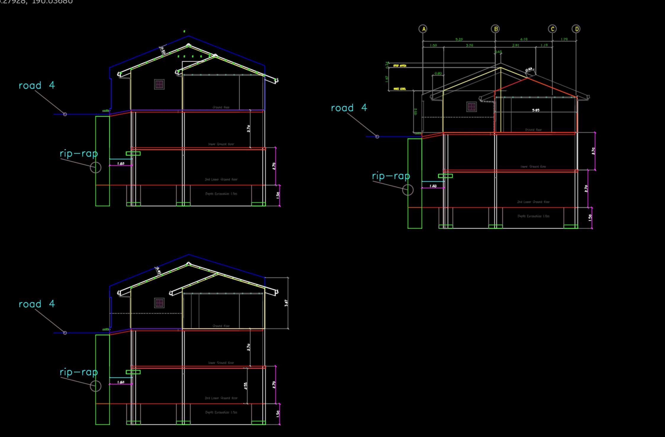
CAD Applications in Civil Engineering
CAD software is widely used in civil engineering to design, analyze, and simulate various aspects of infrastructure projects. By leveraging CAD capabilities, civil engineers can create accurate and detailed digital representations of construction projects, aiding in the planning, visualization, and coordination of complex structures. Here are some key applications of CAD in civil engineering:
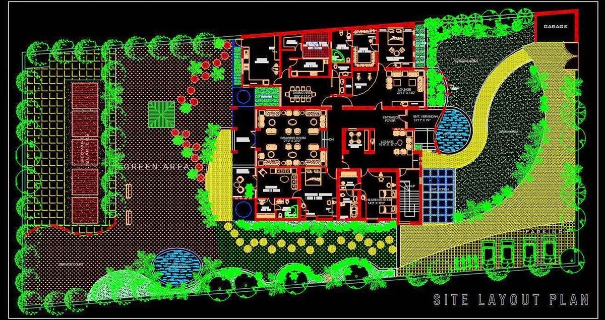
- Site Planning and Design: CAD allows civil engineers to create digital models of landscapes and terrains. They can analyze topographic data, plan site layouts, and design grading and drainage systems to optimize land utilization and prevent potential issues.
- Road and Highway Design: CAD-based civil engineering tools facilitate the design of roads, highways, and transportation networks. Engineers can accurately model road alignments, intersections, signage, and pavement markings, ensuring safe and efficient traffic flow.
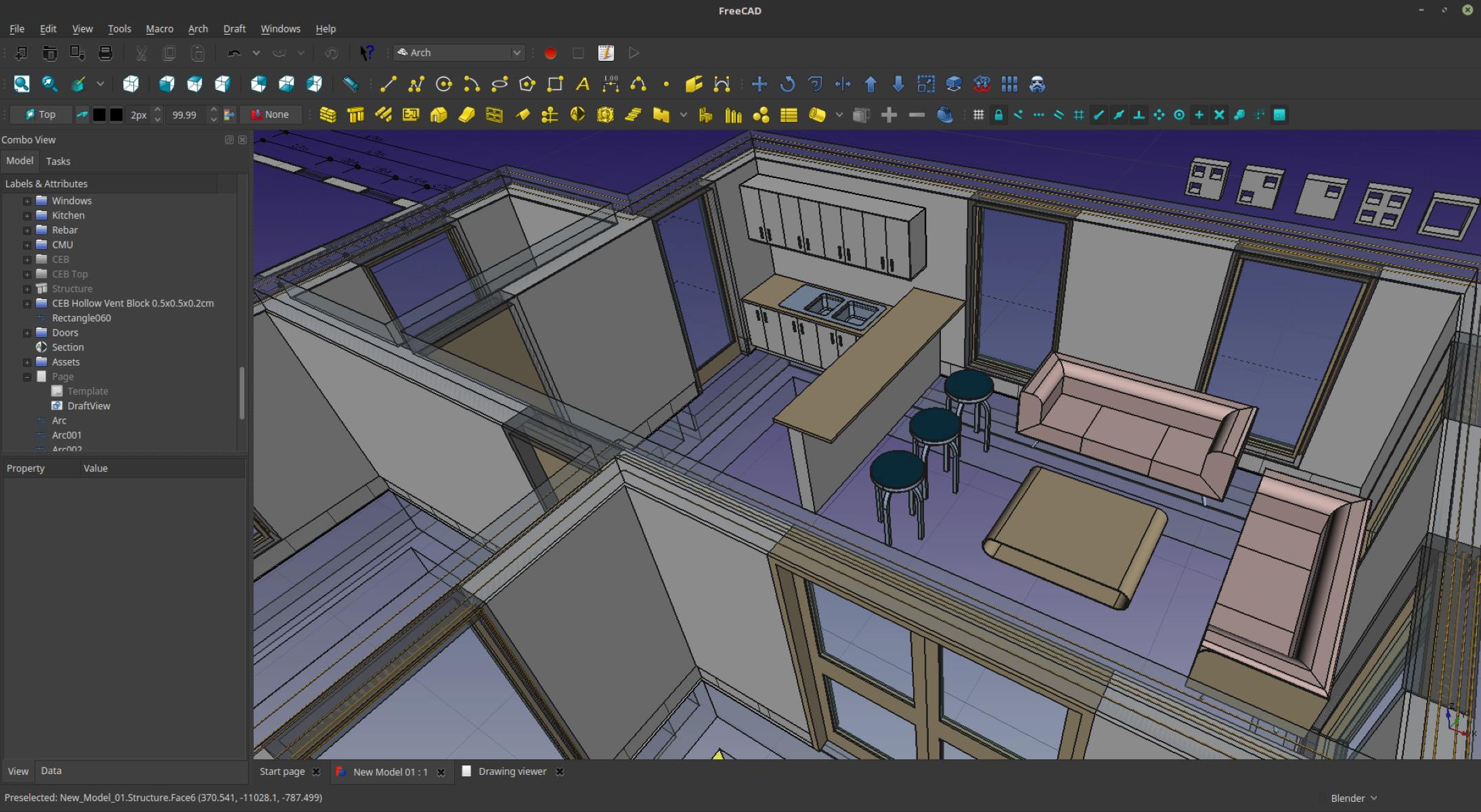
- Bridge and Structural Design: CAD software is used to design and analyze bridges and other structural elements in civil engineering projects. Engineers can create 3D models of bridges, evaluate structural integrity, and optimize designs to meet safety and load-bearing requirements.
- Utility Design: CAD assists in the design and modeling of utility systems, such as water supply networks, sewage systems, and electrical distribution networks. Engineers can plan routes, specify pipe sizes, and simulate flow to optimize utility system performance.
- Geotechnical Analysis: CAD-based civil engineering tools help engineers analyze soil behavior and perform geotechnical analysis. They can study soil types, assess bearing capacities, and identify potential slope instability or settlement issues to optimize foundation designs.
- Quantity Estimation and Costing: CAD software enables engineers to generate accurate quantity takeoffs and cost estimates. By extracting data from the CAD models, engineers can determine material quantities, calculate project costs, and create comprehensive project budgets.
- Visualization and Rendering: CAD tools offer advanced visualization capabilities to create realistic 3D renderings and visualizations of civil engineering projects. This helps stakeholders, clients, and regulatory authorities visualize the proposed structures and make informed decisions.
- Construction Documentation: CAD automates the creation of construction drawings and documentation. Engineers can generate detailed plans, sections, and elevations, along with specifications and construction notes, ensuring accurate and consistent documentation for construction teams.
- Project Coordination: CAD software assists civil engineers in coordinating with other disciplines involved in a project. Engineers can share CAD files, collaborate on a common model, and detect potential clashes or conflicts between different design elements.
- Urban Planning: CAD-based civil engineering tools help in urban planning and development. Engineers can model and simulate urban environments, analyze traffic patterns, and plan for sustainable and efficient urban infrastructure.
The use of CAD in civil engineering revolutionizes the design and planning process, ensuring accurate representation, optimizing efficiencies, and improving collaboration among various stakeholders. It enables civil engineers to design and construct safe, sustainable, and visually appealing infrastructure that meets the demands of modern society.
CAD Applications in Aerospace Engineering
CAD software is a crucial tool in the field of aerospace engineering, enabling engineers to design, analyze, and simulate various aspects of aircraft and spacecraft. With the precision and versatility of CAD tools, aerospace engineers can optimize designs, simulate real-world conditions, and ensure the safe and efficient performance of aerospace systems. Here are some key applications of CAD in aerospace engineering:
- Aircraft Design: CAD software allows aerospace engineers to create detailed 3D models of aircraft, including the fuselage, wings, control surfaces, and engine components. These models serve as the basis for analyzing aerodynamics, structural integrity, and overall aircraft performance.
- Structural Analysis: CAD-based aerospace engineering tools facilitate the analysis of aircraft structures, ensuring their strength, stiffness, and resistance to load conditions. Engineers can perform stress analysis, fatigue analysis, and modal analysis to optimize the design and enhance safety.
- Aerodynamics and Fluid Dynamics: CAD software integrates with computational fluid dynamics (CFD) tools, enabling engineers to simulate and analyze the flow of air around aircraft components. This helps optimize aerodynamic performance, reduce drag, and improve fuel efficiency.
- Thermal Analysis: CAD tools assist aerospace engineers in analyzing heat transfer and thermal behavior in aircraft systems. They can assess temperature distributions, optimize cooling mechanisms, and ensure the safe operation of components under extreme thermal conditions.
- Propulsion System Design: Using CAD, aerospace engineers can model and analyze propulsion systems, including engines, fuel systems, and exhaust systems. This helps optimize engine performance, analyze thermal and fluid dynamics characteristics, and ensure safe and efficient operation.
- Electrical Systems Design: CAD software plays a crucial role in designing electrical systems, avionics, and wiring harnesses in aerospace engineering. Engineers can create detailed electrical schematics, route wires, and analyze electrical characteristics to ensure proper functioning and reliability.
- Collaborative Design: CAD tools enable real-time collaboration among aerospace engineers working on the same design. Design files can be shared and reviewed, allowing for efficient communication and coordination of design changes across multidisciplinary teams.
- Manufacturing and Assembly: CAD software assists in the manufacturing and assembly of aerospace components and systems. It generates detailed manufacturing drawings, assembly instructions, and 3D models for the production of aircraft parts with accuracy and precision.
- Virtual Prototyping: CAD-based simulations allow aerospace engineers to virtually prototype and test aircraft designs. By simulating flight conditions, control systems, and environmental factors, engineers can identify design improvements, optimize performance, and reduce the need for physical prototypes.
- Maintenance and Repair: CAD tools help in the maintenance and repair of aircraft systems. By creating accurate 3D models of aircraft components, engineers can plan and simulate maintenance procedures, identify faults, and facilitate efficient repairs.
The use of CAD in aerospace engineering enhances design precision, optimizes performance, and fosters innovation in the aerospace industry. It empowers engineers to create safer, more efficient, and technologically advanced aircraft and spacecraft, pushing the boundaries of human exploration and transportation.
CAD Applications in Mechanical Engineering
CAD software is an essential tool in the field of mechanical engineering, enabling engineers to design, analyze, and simulate mechanical systems and components. With its comprehensive set of tools and functionalities, CAD has revolutionized the way mechanical engineers conceptualize, develop, and optimize their designs. Here are some key applications of CAD in mechanical engineering:
- Product Design: CAD software allows mechanical engineers to create detailed 3D models of products and components. They can design complex geometries, define material properties, and optimize their designs for functionality, manufacturability, and aesthetics.
- Mechanism Design and Simulation: CAD enables engineers to design and simulate the motion and behavior of mechanical systems and linkages. They can analyze kinematics, calculate forces and torques, and optimize the performance and efficiency of mechanical mechanisms.
- Structural Analysis: CAD-based software provides tools for structural analysis, allowing engineers to evaluate the strength, stiffness, and integrity of mechanical components. They can perform static, dynamic, and modal analysis to optimize designs and ensure safety and reliability.
- Tolerance Analysis: CAD software helps engineers analyze and optimize tolerances in mechanical designs. They can simulate manufacturing variations, assess the impact on assembly, and ensure proper fit and functionality of components within specified tolerances.
- Motion Analysis: CAD tools enable engineers to simulate and analyze the motion of mechanical systems. They can study speed, acceleration, and forces in moving components, optimizing designs for smooth operation, reduced wear, and efficient power transmission.
- Assembly Design and Planning: CAD software assists mechanical engineers in designing and planning the assembly of mechanical components and systems. They can visualize and optimize the assembly sequence, evaluate interferences, and ensure proper fit and alignment of parts.
- Manufacturing and Production Planning: CAD-based tools support manufacturing processes in mechanical engineering. Engineers can generate manufacturing drawings, optimize material usage, plan machining operations, and generate machine code for CNC machines.
- Design Optimization: CAD software offers optimization capabilities, enabling engineers to automatically explore different design options and parameters. They can define optimization goals such as weight reduction or performance improvement to achieve the most efficient and cost-effective designs.
- Prototyping and Rapid Prototyping: CAD facilitates the creation of prototypes by providing 3D digital models that can be used for additive manufacturing or rapid prototyping techniques. This enables engineers to validate designs, conduct physical testing, and accelerate the product development process.
- CAD/CAM Integration: CAD software seamlessly integrates with computer-aided manufacturing (CAM) software, allowing engineers to generate toolpaths for CNC machines. This ensures precise and efficient production of mechanical components and reduces manual programming time.
The use of CAD in mechanical engineering enhances design efficiency, accuracy, and innovation. It enables engineers to create complex geometries, optimize designs for performance, analyze structural integrity, and streamline the manufacturing process. CAD has become an indispensable tool for mechanical engineers in various industries, including automotive, aerospace, machinery, and consumer products.
Conclusion
CAD technology has revolutionized the field of engineering, providing engineers with powerful tools to design, analyze, and optimize a wide range of systems and structures. From mechanical components to complex infrastructure projects, CAD has become an integral part of the engineering workflow, offering numerous benefits and possibilities.
Through CAD, engineers can create accurate and detailed digital models, enabling them to visualize, simulate, and validate their designs before they are physically implemented. This virtual environment not only saves time and resources but also allows for early detection and resolution of potential design flaws, improving overall design quality.
The applications of CAD in different engineering disciplines are vast and varied. In mechanical engineering, CAD facilitates product design, structural analysis, mechanism simulation, and manufacturing optimization. Civil engineers utilize CAD for site planning, infrastructure design, and project coordination. Aerospace engineers rely on CAD for aircraft design, aerodynamics analysis, and structural validation. Electrical engineers harness CAD for electrical system design, schematic creation, and simulation. The applications span across industries, including automotive, aerospace, civil infrastructure, electronics, and many more.
The benefits of using CAD are evident. It increases design efficiency by providing powerful tools for creating, modifying, and visualizing designs. Its simulation and analysis capabilities enable engineers to validate designs, optimize performance, and ensure adherence to safety standards. CAD promotes collaboration and communication among multidisciplinary teams, improving efficiency and reducing errors. Additionally, CAD supports the documentation and manufacturing process, generating accurate drawings and specifications.
In conclusion, CAD has transformed the way engineers approach design and development. It has become an indispensable tool in the engineering profession, empowering engineers to bring their ideas to life with precision, efficiency, and innovation. As technology continues to evolve, CAD will continue to play a vital role, driving advancements in engineering and shaping the future of design and development.
Frequently Asked Questions about How Is CAD Used In Engineering
Was this page helpful?
At Storables.com, we guarantee accurate and reliable information. Our content, validated by Expert Board Contributors, is crafted following stringent Editorial Policies. We're committed to providing you with well-researched, expert-backed insights for all your informational needs.


0 thoughts on “How Is CAD Used In Engineering”